
High-pressure diaphragm compressor, cylinder cover of high-pressure diaphragm compressor, and machining method of cylinder cover

A compressor cylinder and high-pressure diaphragm technology, applied in the field of diaphragm compressors, can solve the problems of large thermal stress on the inner surface of small holes and insufficient expansion of diaphragm compressor exhaust holes, etc., and achieve simple structure, improved strength, and convenient disassembly and assembly Effect

Active Publication Date: 2019-02-19
JIANGSU PERMANENT MACHINERY +1
View PDF6 Cites 4 Cited by
  • Summary
  • Abstract
  • Description
  • Claims
  • Application Information

AI Technical Summary

Problems solved by technology

[0005] The purpose of the present invention is to provide a high-pressure diaphragm compressor and its cylinder head and a processing method for the cylinder head, which can solve the problem that the deformation of the exhaust hole of the diaphragm compressor is greatly restricted due to excessive temperature and cannot be fully expanded, resulting in small The problem of excessive thermal stress on the inner surface of the hole

Method used


Image

  • High-pressure diaphragm compressor, cylinder cover of high-pressure diaphragm compressor, and machining method of cylinder cover
  • High-pressure diaphragm compressor, cylinder cover of high-pressure diaphragm compressor, and machining method of cylinder cover
  • High-pressure diaphragm compressor, cylinder cover of high-pressure diaphragm compressor, and machining method of cylinder cover

Examples


Embodiment Construction

[0034] The present invention will be further described in detail below in conjunction with specific embodiments, which are explanations of the present invention rather than limitations.

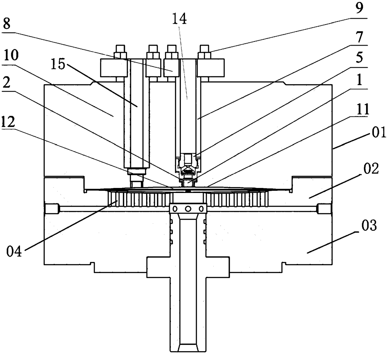
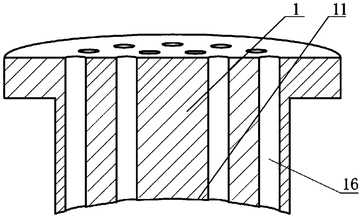
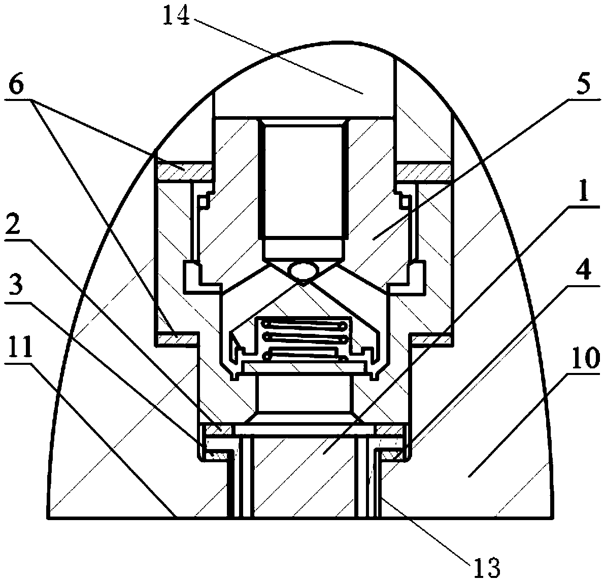
[0035] Such as Figure 1 ~ Figure 2 As shown, the high-pressure diaphragm compressor cylinder head 01 of the present invention includes a cylinder head body 10, and the cylinder head body 10 is provided with an inlet valve hole 15, an exhaust valve hole 14 and an exhaust chamber 13, and the center of the exhaust chamber 13 line, the center line of the exhaust valve hole 14 and the center line of the cylinder head body 10 coincide, the intake valve hole 15 is set near the side of the exhaust valve hole 14, and the exhaust cavity 13 and the exhaust valve hole 14 are connected holes Cavity, the inner wall of the cylinder head body 10 is provided with an arc-shaped groove 11 for forming an air cavity 12 with the diaphragm; an exhaust valve 5 is installed in the exhaust valve hole 14, and an exhau...


PUM


Abstract

The invention discloses a high-pressure diaphragm compressor, a cylinder cover of a high-pressure diaphragm compressor and a machining method of the cylinder cover, and belongs to the field of diaphragm compressors. The cylinder cover of the high-pressure diaphragm compressor comprises a cylinder cover body, wherein cylinder cover body is provided with an exhaust valve, an exhaust hole blockage and an exhaust cavity, the area where exhaust holes are formed in the center of the cylinder cover is excavated to serve as the exhaust cavity, the exhaust hole blockage is independently installed in the exhaust cavity, a corrugated spring is arranged between the exhaust hole blockage and the exhaust valve, the exhaust hole blockage can be used for machining a diaphragm cavity profile of the diaphragm compressor together with the cylinder cover only after the cylinder cover is installed well, and the outer diameter of the exhaust hole blockage is smaller than the inner diameter of the exhaust cavity. According to the high-pressure diaphragm compressor, the cylinder cover of the high-pressure diaphragm compressor and the machining method of the cylinder cover, the problems that under the conditions of high temperature and high pressure, due to the structural limitation of the exhaust holes, the deformation of the exhaust holes is greatly constrained, full expansion cannot be achieved, andthen the thermal stress of the inner surfaces of small holes is quite large are solved, the thermal stress generated by the exhaust holes due to high temperature can be reduced, then the strength ofthe cylinder cover of the high-pressure diaphragm compressor is improved, and normal operation of the diaphragm compressor is not affected.

Description

technical field [0001] The invention belongs to the field of diaphragm compressors, and in particular relates to a high-pressure diaphragm compressor, a cylinder head and a processing method for the cylinder head. Background technique [0002] Diaphragm compressor is a special positive displacement compressor, which completely separates lubricating oil and compressed gas through a set of diaphragms to ensure that the gas is not polluted. It has two characteristics: one is good sealing, no pollution to the compressed medium; the other is large compression ratio, easy to achieve high pressure. Based on these characteristics, diaphragm compressors are widely used in petrochemical, coal chemical, metallurgy, national defense, aerospace, new energy, nuclear power, gas filling, and experimental research departments of modern science and technology. [0003] The deformation and stress of diaphragm compressor cylinder head and other components under high pressure and high temperatu...

Claims


Application Information

Patent Timeline
IPC IPC(8): F04B39/12F04B39/10F04B45/053
CPCF04B39/10F04B39/125F04B45/0533
Inventor 彭学院汪婷陈嘉豪贾晓晗
Owner JIANGSU PERMANENT MACHINERY
Learn More