Multi-tooth-difference annular plate cascading speed reducer

A technology of reducer and ring plate, which is applied in the direction of gear transmission, belt/chain/gear, transmission parts, etc. It can solve the requirements that cannot meet the joint motion requirements of industrial robots, increase the difficulty of crankshaft processing, and make tapered roller bearings easy. Wear and other problems, to achieve the effect of improving anti-gluing ability, light weight, and improving strength

Pending Publication Date: 2019-02-19
CISDI RES & DEV CO LTD
View PDF0 Cites 0 Cited by
  • Summary
  • Abstract
  • Description
  • Claims
  • Application Information

AI Technical Summary

Problems solved by technology

[0003] The RV reducer has the following disadvantages: because there are three crankshafts (that is, power input shafts) for transmission, the three crankshafts are all supported on the bearing positions of the tapered roller bearings of the planet carrier through tapered roller bearings, so the crankshaft The axial precision and radial precision requirements of the tapered roller bearing bearing position are very strict. The two eccentric wheels on the crankshaft are respectively adapted to the cycloidal wheel, and the roundness, cylindricity and phase difference of the two eccentric wheels are very demanding. Strict, the end of the crankshaft must be splined to install the planetary gear, and the phase difference between the spline groove and the eccentric wheel is very strict. These dimensional chains greatly increase the processing difficulty of the crankshaft, and the manufacturing cost is high. The assembly accuracy of the shaft also has high requirements; during use, the tapered roller bearings are easy to wear, resulting in reduced matching accuracy, poor reliability, and reduced service life
The reduction ratio of the single-stage multi-tooth difference cycloidal reducer can not meet the requirements of the joint motion of industrial robots, so it is necessary to study a new type of transmission mechanism to overcome the above shortcomings

Method used


Image

  • Multi-tooth-difference annular plate cascading speed reducer
  • Multi-tooth-difference annular plate cascading speed reducer
  • Multi-tooth-difference annular plate cascading speed reducer

Examples


Embodiment Construction

[0029] The implementation of the present invention will be illustrated by specific specific examples below, and those skilled in the art can easily understand other advantages and effects of the present invention from the contents disclosed in this specification.

[0030] It should be noted that terms such as "upper", "lower", "left", "right", "middle" and "one" quoted in this specification are only for the convenience of description and are not used to limit this specification. The practicable scope of the invention and the change or adjustment of its relative relationship shall also be regarded as the practicable scope of the present invention without any substantial change in the technical content.

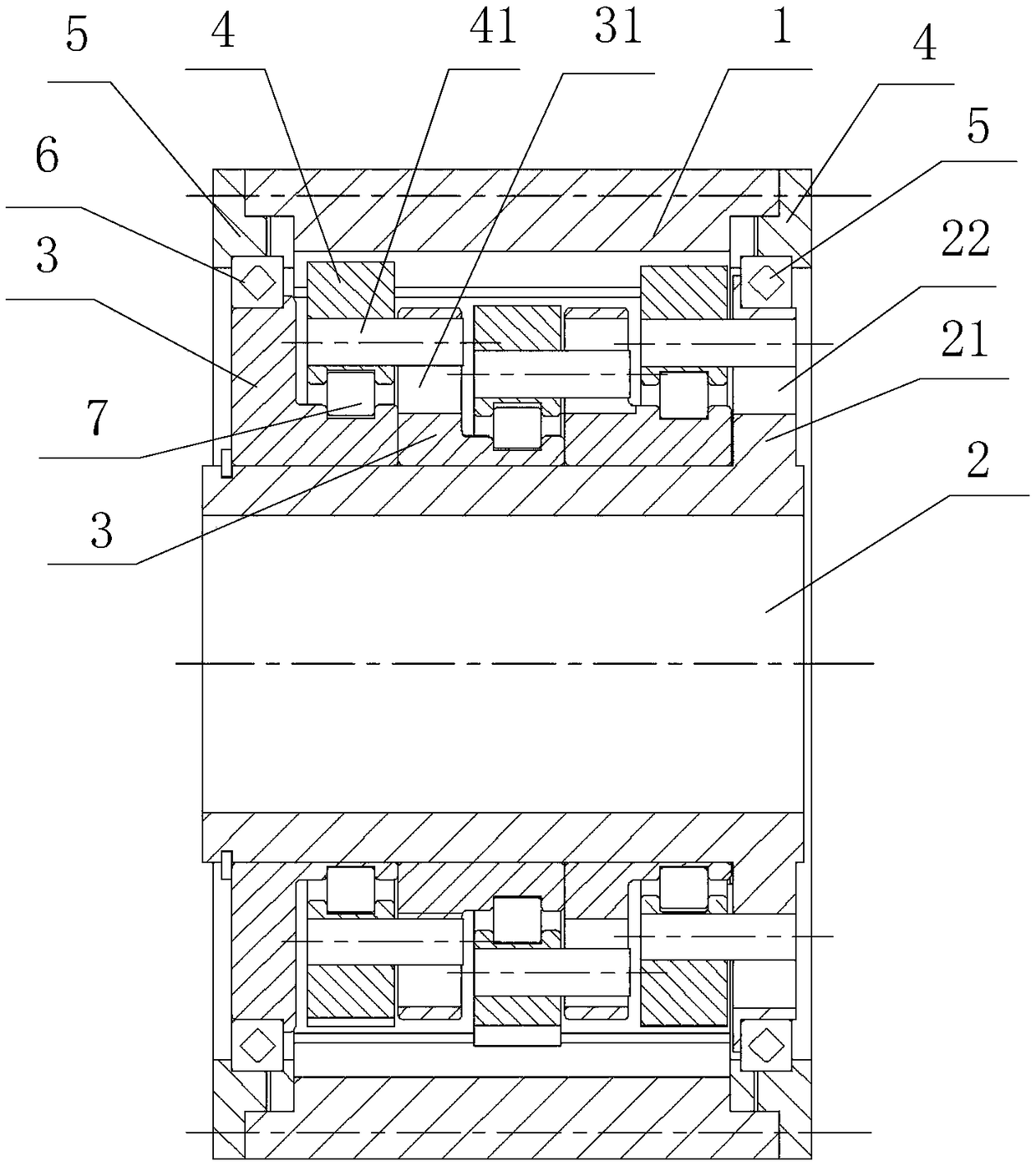
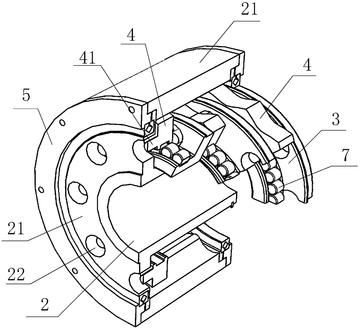
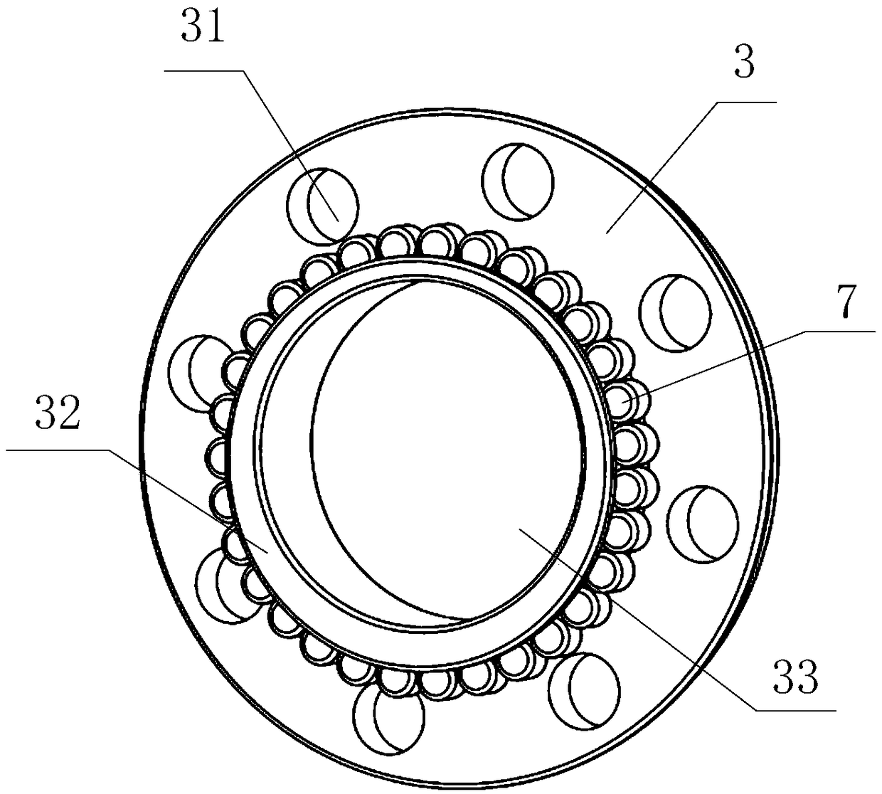
[0031] Such as Figure 1 to Figure 4 As shown, a multi-tooth difference ring-plate cascade reducer includes a central shaft 2, an internal gear 1 and at least two transmission units connected in series; wherein the internal gear 1 is a shell structure with internal teeth, and t...


PUM


Abstract

The invention provides a multi-tooth-difference annular plate cascading speed reducer. The multi-tooth-difference annular plate cascading speed reducer comprises a central shaft, an inner gear and atleast two stages of transmission units connected in series; each stage of the transmission unit comprises a bearing force taking frame and an annular plate swinging wheel, the central shaft is sleevedwith the bearing force taking frames of the all stages of the transmission units, each stage of the annular plate swinging wheel is provided with an outer gear and multiple pin shafts, and the all stages of the annular plate swinging wheels mesh with the same inner gear; multi-tooth-difference cycloidal gear meshing is adopted as the meshing mode; power is transferred to the bearing force takingframe of the next-stage transmission unit through the pin shafts of the last-stage transmission unit, and the current-stage bearing force taking frame acquires rotating power from the last-stage transmission unit and drives the current-stage annular plate swinging wheel to eccentrically rotate; and the final-stage annular plate swinging wheel transfers power to the central shaft through the pin shafts. According to the multi-tooth-difference annular plate cascading speed reducer, assembling is easy, the structural rigidity is high, the multiple stages of the annular plate swinging wheels sharethe inner gear, and the movement transferring precision is higher; and structural arrangement is compact, the rigidity is higher than that of a general cycloidal-pin wheel speed reducer, and the impact resistance and the overload capacity are both improved.

Description

technical field [0001] The invention belongs to the technical field of reducers, and in particular relates to a multi-tooth difference ring plate cascaded reducer. Background technique [0002] Industrial robots widely use RV reducers, which have a series of advantages such as small size, light weight, large transmission ratio range, long life, stable precision, high efficiency, and stable transmission. It is a 2K reducer developed on the basis of traditional planetary transmission. -V-type two-stage planetary transmission pin pendulum reducer with few teeth difference. The first stage transmission of the RV reducer is an involute tooth meshing planetary transmission, and the second stage is a cycloidal pinwheel transmission with a small tooth difference. The cycloidal gear teeth and the pinwheel teeth generally have a difference of 1 tooth. The commonly used RV reducer includes a pin gear housing. The pin gear housing is equipped with a planetary carrier formed by connecti...

Claims


Application Information

Patent Timeline
Patent Type & Authority Applications(China)
IPC IPC(8): F16H1/32F16H1/46F16H57/08
CPCF16H1/32F16H1/46F16H57/08F16H2001/327
Inventor 刘向东刘景亚张燕彤陈波李开兴万小丽
Owner CISDI RES & DEV CO LTD
Why Eureka
Try Eureka