High-speed and high-precision photoelectric encoder with two-piece deployment

A photoelectric encoder, high-precision technology, applied in the direction of instruments, conversion sensor output, measuring devices, etc., can solve the problem of unable to achieve real-time position positioning requirements, unable to work, etc., to achieve large installation tolerance, fewer installation components, coding high precision effect

Inactive Publication Date: 2019-02-19
尹登庆 +1
View PDF0 Cites 2 Cited by
  • Summary
  • Abstract
  • Description
  • Claims
  • Application Information

AI Technical Summary

Problems solved by technology

The processing of the entire signal takes time. In ultra-high-speed, ultra-high-precision applications, such as robots, precision medical equipment, high-precision radar, etc., it cannot meet the real-time position positioning requirements, and even cannot work at ultra-high speed.

Method used


Image

  • High-speed and high-precision photoelectric encoder with two-piece deployment
  • High-speed and high-precision photoelectric encoder with two-piece deployment
  • High-speed and high-precision photoelectric encoder with two-piece deployment

Examples


Embodiment Construction

[0197] Figure 24 Schematic diagram of the illustrated embodiment-2D bidirectional light splitting and unidirectional coding based on precision machining process 2 8 Passive optical encoding components are segmented. This part is the 4 code BAR of the rotor assembly-passive optical coding part. Horizontal 3mm, 4bite MSB code, vertical incidence left and right light splitting unit, 4bite LSB code are constructed from left to right.

[0198] The photo was taken non-vertically. It can work normally if the distance between the stator assembly and PCBA is within 15mm without the light exit lens. If it is necessary to increase the distance between the stator assembly-PCBA and the rotor assembly-passive optical encoding component, the light exit lens or the light exit lens and the light receiving port collimating lens need to be used to constrain and process the encoded beam.

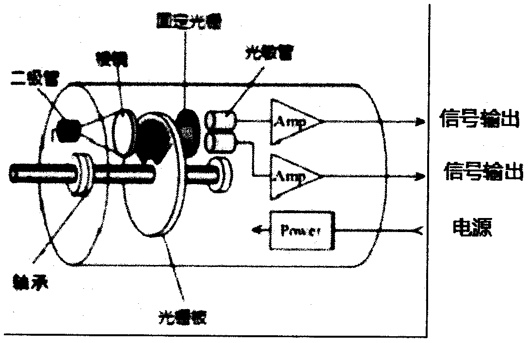
[0199] Figure 25 Schematic diagram of the illustrated embodiment-PCBA of the stator assembly. A light source ...


PUM


Abstract

The invention relates to a photoelectric encoder suitable for various motors, in particular high-speed and high-precision motors, and supports 32 million lines and 600,000 rpm. The photoelectric encoder is divided into a passive optical coding component mounted on a rotor, a light source + photoelectric conversion + a data acquisition processing module mounted on a stator. The encoder supports absolute and incremental encoding. The passive optical components of different specifications are manufactured through mass production or precision machining in the form of matryoshka dolls by using integrated circuits or micro-electromechanical and precision mold processes. Higher speeds and resolutions are supported as the manufacturing processes are improved. The encoder uses a microlens array toincrease sensitivity, and uses the microlens array to form a spot of a special pattern, thereby increasing a tolerance threshold and facilitating to install and use. The performance indicators of thelight source, a photosensor, a lens array, the passive optical coding component, etc. used by the encoder are related to coding accuracy, the speed, and device size.

Description

Technical field [0001] The invention belongs to the field of motor photoelectric encoders, and relates to a precision photoelectric encoder of a rotary or linear motor, especially a high-speed, high-precision and long-time use encoder, which uses passive optics or laser components to encode positions, and a photosensitive device array is parallel The technology of reading information and processing data. The preparation of devices involves integrated circuits, micro-electromechanical (MEMS), micro-optical electromechanical (MOEMS), coding, data processing and other cross-cutting fields. Background technique [0002] The code disc of the photoelectric encoder is fixed on the main shaft and rotates together with the main shaft. The slit disc is fixed, and the light emitting element emits light. The relative movement of the code disc and the slit disc produces moiré fringes and transmits it to the receiving element; then the receiving element Convert the received light signal of the...

Claims


Application Information

Patent Timeline
Patent Type & Authority Applications(China)
IPC IPC(8): G01D5/347
CPCG01D5/3473
Inventor 袁戎其他发明人请求不公开姓名
Owner 尹登庆
Why Eureka
Try Eureka