
Three-dimensional universal full-angle optical measurement platform for space optical remote sensor

A space optical remote sensing and optical measurement technology, which is applied in the testing of optical instruments, measuring devices, and testing of machinery/structural components, etc., can solve the lack of special ground simulation devices for on-board optical instruments, the complex and difficult test processes and tooling structures, etc. problems, to achieve the effect of easy expansion of functions, high degree of freedom of installation, and simplified structure

Active Publication Date: 2019-02-19
HEFEI INSTITUTES OF PHYSICAL SCIENCE - CHINESE ACAD OF SCI
View PDF5 Cites 8 Cited by
  • Summary
  • Abstract
  • Description
  • Claims
  • Application Information

AI Technical Summary

Problems solved by technology

[0003] The purpose of the present invention is to provide a three-dimensional universal full-angle optical measurement platform for space optical remote sensors, which is a three-dimensional, multi-degree-of-freedom, and full-view optical installation, testing, and calibration system for space optical remote sensors. Scattering, reflection, and converging output of the optical path of the instrument, and an optical and mechanical system that freely cooperates with the optical path of the instrument, solves the lack of special ground simulation devices for on-board optical instruments, complex test procedures and tooling structures, and actual system installation, testing, and calibration difficult puzzle

Method used


Image

  • Three-dimensional universal full-angle optical measurement platform for space optical remote sensor

Examples


Embodiment Construction

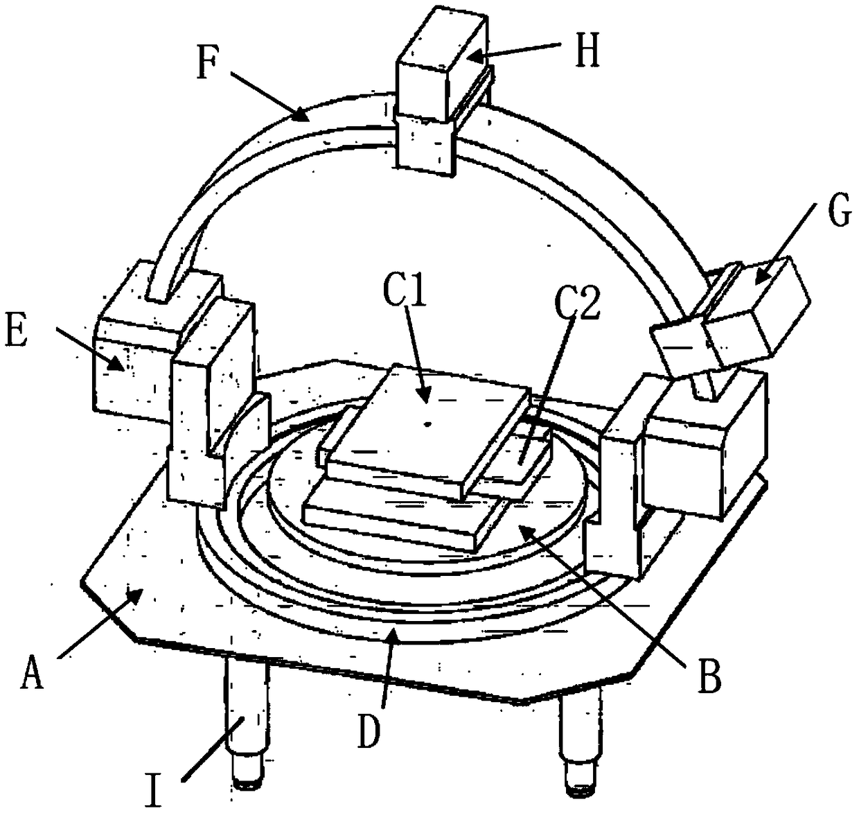
[0020] Such as figure 1 As shown, the three-dimensional universal all-angle optical measurement platform for space optical remote sensors includes a stable platform A, a lifting platform B, a translation platform, an azimuth circular guide rail D, a pitch arm E, a rolling guide rail F, a light source mobile platform G and a detector Mobile platform H; the stable platform A is equipped with a lifting platform B and an azimuth circular guide rail D surrounding the lifting platform B, and a translation platform is installed on the lifting platform B, and the translation platform includes an X-direction translation platform C1 and a Y-direction stacked up and down. On the translation platform C2, a pair of pitching arms E are symmetrically slidably installed on the azimuth circular guide rail D, and a rolling guide rail F is mounted on the two pitching arms E, and the rolling guide rail F is a semicircular structure. Light source mobile platform G and detector mobile platform H; i...


PUM

PropertyMeasurementUnit
Heightaaaaaaaaaa

Abstract

The invention discloses a three-dimensional universal full-angle optical measuring platform for a space optical remote sensor, comprising a stable platform, a lifting platform, a translation platform,an azimuth circular guide rail, a pitching arm, a rolling guide rail, a light source moving platform, and a detector moving platform. The lifting platform and the azimuth circular guide rails surrounding the lifting platform are mounted on the stable platform. The lifting platform is provided with the translation platform which comprises a stacked X-direction and Y-direction translation platform.A pair of pitching arms are mounted symmetrically and slidably on the azimuth circular guide rail. The two pitching arms are erected with the rolling guide rail which has a semicircular structure. Alight source moving platform and a detector moving platform are slidably mounted on the rolling guide rail. In the process of measurement, assembly and calibration, a tested instrument is placed on the translation platform, and independent changes in seven variables such as the three-dimensional coordinates of the position of the tested instrument, the incident azimuth angle and the zenith angle of the light source, and the receiving azimuth and zenith angle of the detector are achieved by an automatic control system and an actuator. The function of the platform is easy to expand and has highpracticability.

Description

technical field [0001] The invention relates to the field of optical measurement devices, in particular to a three-dimensional universal all-angle optical measurement platform for a space optical remote sensor. Background technique [0002] A spaceborne space optical remote sensor analyzes the distribution and changes of atmospheric components by detecting the multi-channel broadband optical radiation reflected and scattered by the earth's atmosphere or surface. The assembly and debugging of the optical components of the instrument is the key point of the system assembly; the test of the optical performance of the instrument is the key to measure whether the system can work normally; the ground calibration of the instrument is the premise and basis for the quantification of remote sensing data. In order to provide optical measurement means for instrument installation, testing and calibration, improve the quality of instrument installation and adjustment, provide quantitative...

Claims


Application Information

Patent Timeline
IPC IPC(8): G01M11/00
CPCG01M11/00
Inventor 曾议刘凤垒代海山司福祺陈军汪世美
Owner HEFEI INSTITUTES OF PHYSICAL SCIENCE - CHINESE ACAD OF SCI
Learn More