Precise positioning method for nano-displacement table based on partially coherent light

A technology of precise positioning and coherent light, which is applied in the field of flying precision engineering, can solve the problems of short coherent distance of coherent light, smaller measurement range, and measurement data processing, so as to avoid random noise and improve accuracy

Active Publication Date: 2019-02-19
FUDAN UNIV
View PDF6 Cites 3 Cited by
  • Summary
  • Abstract
  • Description
  • Claims
  • Application Information

AI Technical Summary

Problems solved by technology

In addition, the surface characteristics of the workpiece will change during the micro-nano laser process, causing the laser signal to reflect, scatter and diffract on the surface, and the detector cannot fully collect the reflected signal
These problems are the inherent errors of laser interferometry, which are difficult to solve effectively by improving the optical path or data processing; if a partially coherent light source is used, the accuracy and reliability of displacement measurement can be effectively improved, but the coherence distance of partially coherent light is relatively short, resulting in The measurement range becomes smaller, and the interference intensity change of partially coherent light is more complicated than laser interferometry, how to process the measurement data becomes a difficult problem

Method used


Image

  • Precise positioning method for nano-displacement table based on partially coherent light
  • Precise positioning method for nano-displacement table based on partially coherent light
  • Precise positioning method for nano-displacement table based on partially coherent light

Examples


Embodiment 1

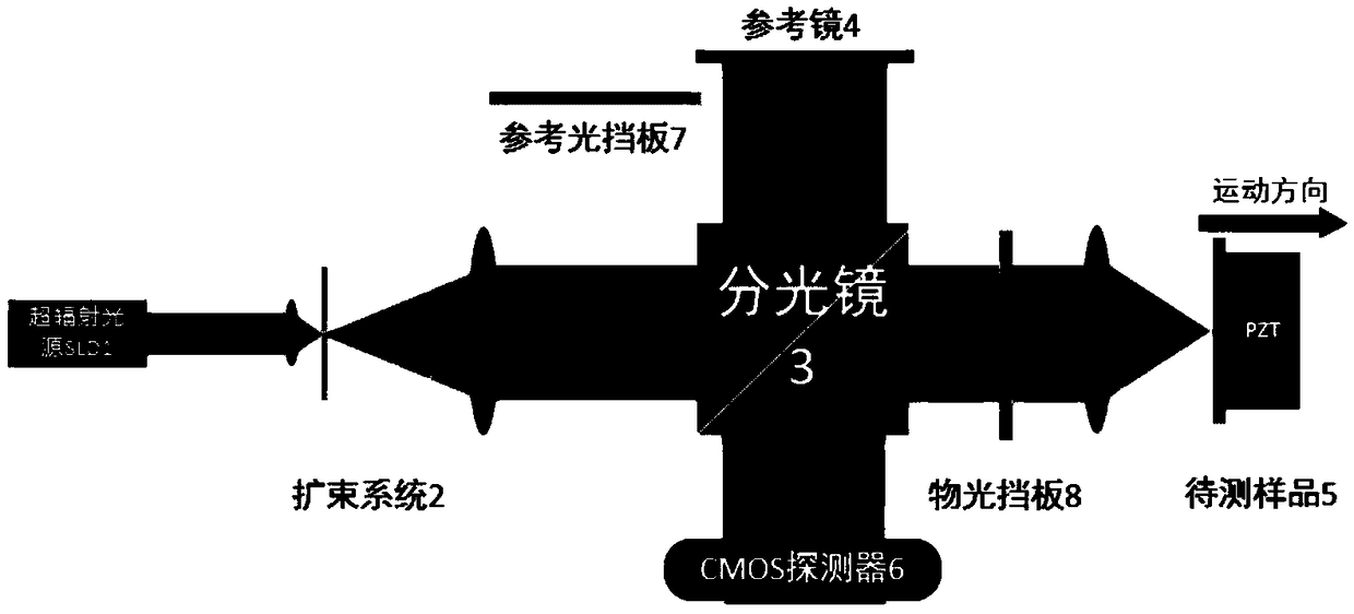
[0032] Embodiment 1: as figure 1 As shown, the dual-channel optical path consists of a superluminescent diode SLD light source, a beam expander system, a beam splitter, a reference mirror, a sample to be tested, a CMOS detector, a reference light baffle, and an object light baffle. Partially coherent light is emitted from the SLD and widened by the beam expander system, and then split into two beams by the beam splitter, reflected by the reference mirror and the sample to be tested, and then combined by the beam splitter to reach the CMOS detector. The reference light baffle is used for preliminary focusing and can block the beam passing through the reference mirror, and the object light baffle is used for light source calibration and will block the beam passing through the sample to be measured.

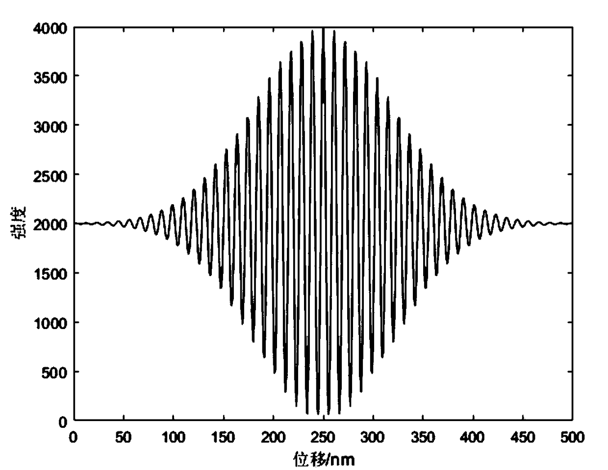
[0033] In the measurement process, after the optical path is built, the object light baffle is firstly added, and its intensity change is measured by CMOS, and the intensity distrib...


PUM


Abstract

The invention belongs to the field of precision engineering, and particularly relates to a precise positioning method for a nano-displacement table based on partially coherent light. The method comprises the following steps of: employing a low-coherence light source, and using an interference light path to determine the optimal focusing position according to the contrast ratio of the interferenceimage; and recording the change in the interference fringes as the longitudinal movement of an objective lens, using the fitting algorithm in the invention to obtain the envelope curve of the interference intensity, calculating the physical parameters of the light beam, and determining the relative displacement through the phase relationship between the interference patterns. The algorithm takes into account the error effect, and is high in universality and anti-noise capability. The method has the advantages that the focusing and the displacement measurement can be achieved at the same time by adopting a partially coherent light source, and the higher repetition positioning precision can be obtained, and the method has important significance in improving the efficiency and the reliabilityof micro-nano machining.

Description

technical field [0001] The invention belongs to the field of precision engineering, and specifically relates to a method for precise positioning of a nanometer displacement platform based on partially coherent light. Background technique [0002] In modern micro-nano processing and precision, laser positioning systems are usually used to measure the displacement of processed samples. However, due to the strong coherence of the light source in laser measurement technology, there will be unavoidable interference from stray fringes and speckles. It affects the reliability of the measurement and also reduces the accuracy of the measurement. Moreover, interferometric measurement uses the wavelength of the laser as a reference, which is very sensitive to environmental disturbance and vibration, so the measurement environment needs to be strictly controlled. In addition, the surface characteristics of the workpiece will change during the micro-nano laser process, causing the laser...

Claims


Application Information

Patent Timeline
Patent Type & Authority Applications(China)
IPC IPC(8): G01S17/06G01B11/00
CPCG01B11/00G01S17/06
Inventor 程宇张祥朝徐敏袁鹤
Owner FUDAN UNIV
Why Eureka
Try Eureka