
Dual three-phase permanent magnetic synchronous motor, electric automobile and method of dual three-phase permanent magnetic synchronous motor

A dual-phase permanent magnet, synchronous drive technology, applied in electric vehicles, motors, electric components, etc., can solve the problems of low utilization rate of motor iron core materials, high motor thermal load, and difficulty in motor heat dissipation, reducing The effect of magnetic flux leakage at the end, increasing the total electric heating load, and reducing the iron loss

Active Publication Date: 2019-02-19
SHANDONG UNIV
View PDF6 Cites 2 Cited by
  • Summary
  • Abstract
  • Description
  • Claims
  • Application Information

AI Technical Summary

Problems solved by technology

[0009] However, according to the knowledge of the inventors, most current multi-phase motors have the problems of end magnetic flux leakage and low utilization rate of motor iron core materials. Outside the rotor, it is the outer stator. The heat generated by the motor is concentrated in the axial direction of the motor, and the thermal load of the motor is very high. Moreover, the inner stator is not connected to the external environment, so it is difficult for the motor to dissipate heat.

Method used


Image

  • Dual three-phase permanent magnetic synchronous motor, electric automobile and method of dual three-phase permanent magnetic synchronous motor
  • Dual three-phase permanent magnetic synchronous motor, electric automobile and method of dual three-phase permanent magnetic synchronous motor
  • Dual three-phase permanent magnetic synchronous motor, electric automobile and method of dual three-phase permanent magnetic synchronous motor

Examples


Embodiment Construction

[0060] The present disclosure will be further described below in conjunction with the accompanying drawings and embodiments.

[0061] It should be pointed out that the following detailed description is exemplary and intended to provide further explanation to the present application. Unless defined otherwise, all technical and scientific terms used herein have the same meaning as commonly understood by one of ordinary skill in the art to which this application belongs.

[0062] It should be noted that the terminology used here is only for describing specific implementations, and is not intended to limit the exemplary implementations according to the present application. As used herein, unless the context clearly dictates otherwise, the singular is intended to include the plural, and it should also be understood that when the terms "comprising" and / or "comprising" are used in this specification, they mean There are features, steps, operations, means, components and / or combinati...


PUM


Abstract

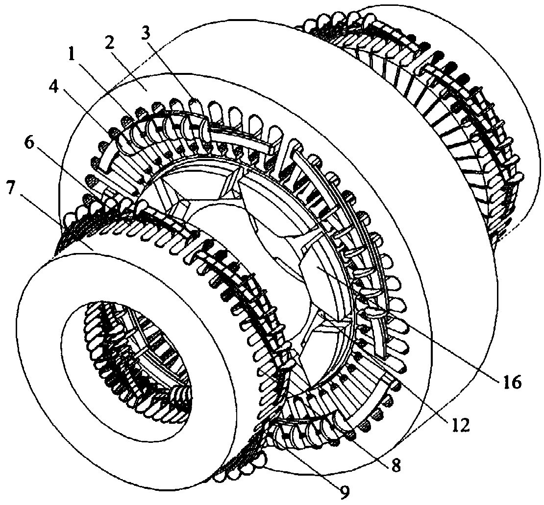
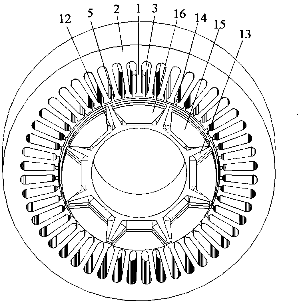
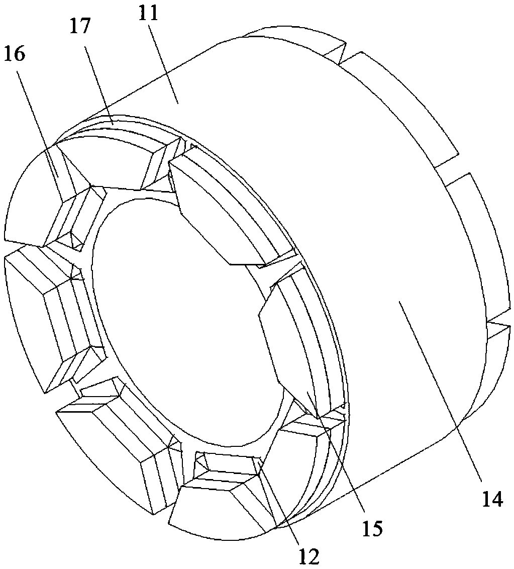
The invention provides a dual three-phase permanent magnetic synchronous motor, an electric automobile and a method of the dual three-phase permanent magnetic synchronous motor. Compared with a traditional multi-phase motor, dual three-phase permanent magnetic synchronous motor has the advantages that by placing an axial stator on an end portion of a rotor, the end portion of the rotor is made full use of, magnetic leakage effect of the end portion is reduced, a use ratio of a permanent magnet is increased, a better magnetism gathering effect can be generated since a permanent magnet is placedon a surface of an axial end of the rotor of the motor, the motor is enabled to be higher in iron core magnetic flux density and air gap magnetic flux density, a use ratio of an iron core material ofthe motor is increased, weight of the motor is reduced, power density and torque density of the motor are increased remarkably, and the weight of the motor is furtherly reduced; a magnetic circuit ofan axial end portion, without the permanent magnet, of the rotor of the motor is parallelly connected with a radial magnetic circuit of the motor, by regulating the mixed magnetic circuits, an operation range of constant power of the motor can be enlarged, and the defect that the power density and efficiency are decreased after the operation range of the constant power of a traditional permanentmagnetic synchronous motor is enlarged is overcome.

Description

technical field [0001] The disclosure relates to a dual-three-phase permanent magnet synchronous drive motor, an electric vehicle and a method thereof. Background technique [0002] The statements in this section merely provide background information related to the present disclosure and do not necessarily constitute prior art. [0003] With the improvement of high temperature resistance and price reduction of permanent magnet materials, permanent magnet motors have been widely used in national defense, industry, agriculture and daily life, and are developing in the direction of high power, high functionality and miniaturization. The variety and application fields of magneto are constantly expanding. At present, the power of permanent magnet motors ranges from a few milliwatts to thousands of kilowatts, and the application scope ranges from small toy motors to large permanent magnet motors used in ship traction. They are used in various aspects of the national economy, dail...

Claims


Application Information

Patent Timeline
Patent Type & Authority Applications(China)
IPC IPC(8): H02K16/00H02K1/27H02K1/16H02P25/022
CPCH02K1/16H02K1/2706H02K1/2793H02K16/04H02P25/022H02P25/024H02P2207/05Y02T10/64
Inventor 王道涵彭晨
Owner SHANDONG UNIV
Learn More