Multi-stator parallel pole type six-phase permanent magnet synchronous drive motor, application and method thereof

A permanent magnet synchronous driving motor technology, applied in the direction of magnetic circuit rotating parts, magnetic circuits, electromechanical devices, etc., can solve the problem of affecting the constant power operating range of the motor, the low utilization rate of the motor iron core material, and the poor adjustment ability of the motor magnetic flux and other problems, to achieve the effects of reducing the magnetic flux leakage effect at the end, low iron loss, and improving power density

Active Publication Date: 2020-03-31
SHANDONG UNIV
View PDF6 Cites 0 Cited by
  • Summary
  • Abstract
  • Description
  • Claims
  • Application Information

AI Technical Summary

Problems solved by technology

[0009] However, according to the inventor's understanding, most of the current multi-phase motors have end magnetic flux leakage, low utilization rate of motor iron core materials, and poor magnetic flux adjustment ability of the motor, which is not conducive to the motor's weak magnetic field speed expansion, thus affecting the motor. The constant power operating range of

Method used


Image

  • Multi-stator parallel pole type six-phase permanent magnet synchronous drive motor, application and method thereof
  • Multi-stator parallel pole type six-phase permanent magnet synchronous drive motor, application and method thereof
  • Multi-stator parallel pole type six-phase permanent magnet synchronous drive motor, application and method thereof

Examples


Embodiment 1

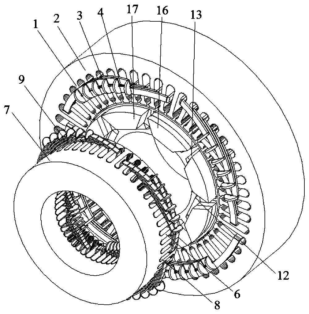
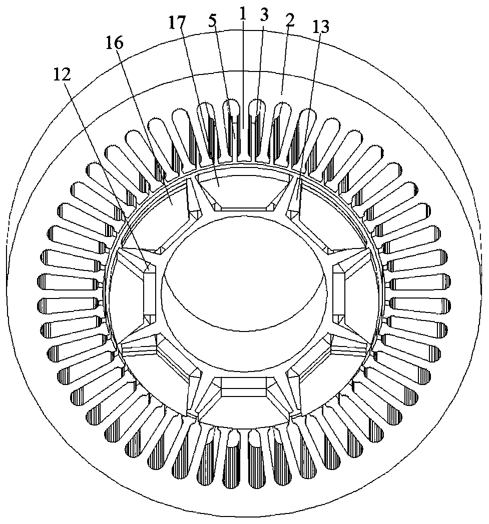
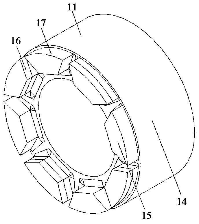
[0074] As shown in Figure 1(a)-Figure 1(e), the number of motor phases in this embodiment is 6, the number of radial stator teeth is 48, the number of axial stator teeth is 48, the number of rotor slots is 8, and the number of radial magnetic poles is 8 , the number of axial magnetic poles is 8, one end of the rotor has a fan ring structure, every other fan ring on the fan ring is placed with a permanent magnet in the form of parallel poles, and the permanent magnet on the fan ring is placed on the pole of the iron core side The polarity is opposite to the axial flux polarity formed by the permanent magnets in the rotor slots. This embodiment includes a radial stator, an axial stator and a rotor. The radial stator is made of laminated silicon steel sheets. The radial stator includes radial stator teeth 1, radial stator yokes 2 and radial stator slots 3. The radial stator A radial armature winding 4 is placed in the slot 3. The radial armature winding 4 can be divided into dist...

Embodiment 2

[0076] As shown in Figure 2(a)-Figure 2(e), the main difference between Embodiment 2 and Embodiment 1 is that (1) there are axial stators at both ends of the motor in Embodiment 2, and the motor has soft magnetic The two ends of the composite rotor core are processed into the shape of the fan ring to form the axial magnetic poles, but in the first embodiment, only one end of the motor has an axial stator, and only one end of the motor rotor core is processed into a fan ring. The shape forms the axial magnetic poles. (2) In the second embodiment, since both ends of the rotor are processed into the shape of fan rings, permanent magnets are attached to every other fan ring at the two ends of the rotor in a parallel pole structure, and the two ends The permanent magnets at the top are at the same axial position, and the structure in the second embodiment can eliminate the unbalanced magnetic pulling force on the rotor because there are stators at both ends of the rotor. In this em...

Embodiment 3

[0079]As shown in Figure 3(a)-Figure 3(e), the main difference between Embodiment 3 and Embodiment 2 is that there are fan ring structures on both ends of the rotor of the motor, and the permanent magnets on the fan ring structure are arranged every other fan ring structure. The rings are arranged in a parallel-pole manner, but the permanent magnet surfaces at both ends are attached to different axes, that is, they are staggered when viewed from the axial direction. In this embodiment, the number of motor phases is 6, and the number of radial stator teeth is 48. , the number of axial stator teeth is 48, the number of rotor slots is 8, the number of radial magnetic poles is 8, and the number of axial magnetic poles is 8. Both ends of the rotor are designed with fan ring structures, and the permanent magnets on the fan rings are separated by a fan ring. The rings are arranged in the form of parallel poles, and the permanent magnets on the fan rings at both ends of the rotor are o...


PUM


Abstract

The invention provides a multi-stator cis-pole six-phase permanent magnet synchronous driving motor, an application and a method of the motor. The motor comprises a radial stator, an axial stator anda rotor, the rotor is mounted in the radial stator in a sleeving manner, the rotor and the radial stator are coaxially distribute, at least one end of the rotor is provided with the axial stator, theaxial stator and the rotor are concentrically distributed, a radial winding is arranged in a stator groove of the radial stator, an axial winding is arranged in a stator groove of the axial stator, permanent magnets are placed in the stator grooves, the same polarities of the permanent magnets in the stator grooves are opposite, radial magnetic flux and axial magnetic flux are generated on the rotor through magnetic gathering effects, a sector-shaped ring structure is arranged at the end of the rotor, permanent magnets are placed on sector-shaped rings at the intervals of one sector-shaped ring in a cis-pole manner, and polarity generated by the permanent magnets pasted on the sector-shaped rings on the inner side of a rotor core is opposite to that generated by the permanent magnets in the stator groove on the rotor core.

Description

technical field [0001] The disclosure relates to a multi-stator parallel pole six-phase permanent magnet synchronous drive motor, an application and a method thereof. Background technique [0002] The statements in this section merely provide background information related to the present disclosure and do not necessarily constitute prior art. [0003] With the improvement of high temperature resistance and price reduction of permanent magnet materials, permanent magnet motors have been widely used in national defense, industry, agriculture and daily life, and are developing in the direction of high power, high functionality and miniaturization. The variety and application fields of magneto are constantly expanding. At present, the power of permanent magnet motors ranges from a few milliwatts to thousands of kilowatts, and the application scope ranges from small toy motors to large permanent magnet motors used in ship traction. They are used in various aspects of the nationa...

Claims


Application Information

Patent Timeline
Patent Type & Authority Patents(China)
IPC IPC(8): H02K16/04H02K1/27
CPCH02K1/2773H02K1/2786H02K16/04
Inventor 王道涵彭晨王秀和
Owner SHANDONG UNIV
Why Eureka
Try Eureka