Multi-channel ROF system and implementation method

A multi-channel, plug-in box technology, applied in the field of optical communication, can solve the problems of inconvenient application, high power consumption, and low density of phased array radar, and achieve the effect of light weight, low power consumption, and increased density

Inactive Publication Date: 2019-02-19
TOEC TECH
View PDF0 Cites 6 Cited by
  • Summary
  • Abstract
  • Description
  • Claims
  • Application Information

AI Technical Summary

Problems solved by technology

[0004] The purpose of the present invention is to solve the problem that traditional ROF products have large volume, low density, high power consumption, and inconvenient application in the fields of phased array radar,

Method used


Image

  • Multi-channel ROF system and implementation method
  • Multi-channel ROF system and implementation method
  • Multi-channel ROF system and implementation method

Examples


Embodiment 1

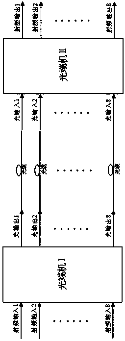
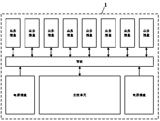
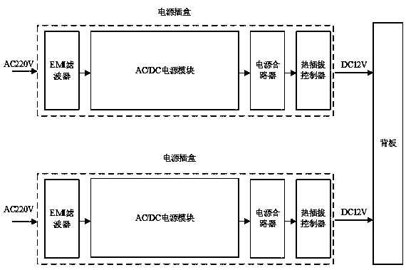
[0053] Optical transceiver I configuration: 1U chassis 1, eight-way optical transmission box, one main control unit, two power box and backplane.

[0054] Optical transceiver II configuration: 1U chassis 1, eight optical receiving boxes, a main control unit, two power boxes and a backplane.

[0055] The eight channels of radio frequency signals are respectively input to the eight channels of optical transmitting box of the optical transceiver Ⅰ, and the "electrical-optical" conversion is performed, and the eight channels of optical signals are output. The transmitted eight-channel optical signals are converted by "optical-to-electrical" to restore eight-channel radio frequency signals, and complete the long-distance transmission of eight-channel radio frequency signals from optical transceiver Ⅰ to optical transceiver Ⅱ; and vice versa.

Embodiment 2

[0057] Optical transceiver I configuration: 1U chassis 1, one optical transmitting box, seven optical receiving boxes, one main control unit, two power supply boxes and backplane.

[0058] Optical transceiver II configuration: 1U chassis 1, one optical receiving box, seven optical transmitting boxes, one main control unit, two power supply boxes and backplane.

[0059] One channel of radio frequency signal is respectively input to one channel of optical transmission box of optical transceiver Ⅰ for "electrical-optical" conversion, and one channel of optical signal is output, and one channel of optical signal is transmitted to one channel of optical receiving box of optical transceiver II through optical cable, and the optical receiving box pairs the transmission The incoming optical signal undergoes "optical-to-electrical" conversion to restore a single radio frequency signal; the seven radio frequency signals are respectively input to the seven optical transmission boxes of th...

Embodiment 3

[0061] Optical transceiver I configuration: 1U chassis 1, two-way optical transmitting box, six-way optical receiving box, one main control unit, two power supply boxes and backplane.

[0062] Optical transceiver II configuration: 1U chassis 1, two-way optical receiving box, six-way optical transmitting box, one main control unit, two power supply boxes and backplane.

[0063] The two-way radio frequency signals are respectively input to the two-way optical transmitting box of the optical transceiver Ⅰ, and the "electrical-optical" conversion is performed, and the two-way optical signals are output. The two-way optical signals are respectively transmitted to the two-way optical receiving box of the optical transceiver Ⅱ through the optical cable. The optical receiving box performs "optical-to-electrical" conversion on the transmitted two-way optical signal, and restores the two-way radio frequency signal; the six-way radio frequency signal is respectively input to the six-way o...


PUM


Abstract

The invention relates to a multi-channel ROF system and an implementation method. Eight paths of radio frequency signals are respectively input to eight optical transfer insertion boxes of optical terminal equipment I for electro-optical transform; eight paths of optical signals are output; the eight paths of optical signals are respectively transmitted to eight optical receiving insertion boxes of optical terminal equipment II through an optical cable; the optical receiving insertion box carries out optical-electro transform on the eight paths of transmitted optical signals; eight paths of radio frequency signals are restored; remote transmission of the eight paths of radio frequency signals is completed; or the eight paths of radio frequency signals are respectively input to eight optical transfer insertion boxes of the optical terminal equipment II for electro-optical transform; eight paths of optical signals are output; the eight paths of optical signal are respectively transmittedto eight optical receiving insertion boxes of the optical terminal equipment I through the optical cable; the optical receiving insertion box performs optical-electro transform on the eight paths oftransmitted optical signals; eight paths of radio frequency signals are restored; and remote transmission of the eight paths of the radio frequency signals is completed. The invention is a flexible and stable multi-channel ROF system with small volume, light weight, high density and low power consumption.

Description

technical field [0001] The present invention relates to the technical field of optical communication, in particular to a multi-channel ROF system and an implementation method for long-distance optical transmission of multi-channel radio frequency signals. Background technique [0002] The so-called ROF technology (radio frequency optical transmission) uses optical fiber as the transmission medium to realize broadband wireless signal transmission, exchange, delay and other functions, and fully utilizes the advantages of optical fiber transmission such as small attenuation, long distance, and strong anti-interference ability, and can be widely used It is widely used in satellite communication, remote antenna, broadband radio frequency microwave signal transmission, local oscillator signal transmission, optical fiber delay, electronic countermeasures, airborne and shipborne communications and other fields. [0003] At present, with the continuous maturity of ROF technology, the...

Claims


Application Information

Patent Timeline
IPC IPC(8): H04B10/2575
CPCH04B10/25752H04B10/25756
Inventor 王卫龙韩哲王尧徐文大
Owner TOEC TECH
Why Eureka
Try Eureka