Tilting mechanism with control surface

A technology of a tilting mechanism and a rudder surface, applied in the field of aircraft, can solve the problems of the backward tilting rotor affecting aerodynamic performance, poor chain transmission stability, etc., and achieve the effects of low installation accuracy, increased aerodynamic efficiency, and strong resistance.

Pending Publication Date: 2019-02-22
NORTHWESTERN POLYTECHNICAL UNIV
View PDF2 Cites 4 Cited by
  • Summary
  • Abstract
  • Description
  • Claims
  • Application Information

AI Technical Summary

Problems solved by technology

[0005] In order to overcome the poor stability of the chain transmission in the prior art, and the deficiency that the rear tilting rotor is located above the fuselage and affects the aerodynamic performance, the present invention proposes a tilting mechanism with a rudder surface

Method used


Image

  • Tilting mechanism with control surface
  • Tilting mechanism with control surface
  • Tilting mechanism with control surface

Examples


Embodiment Construction

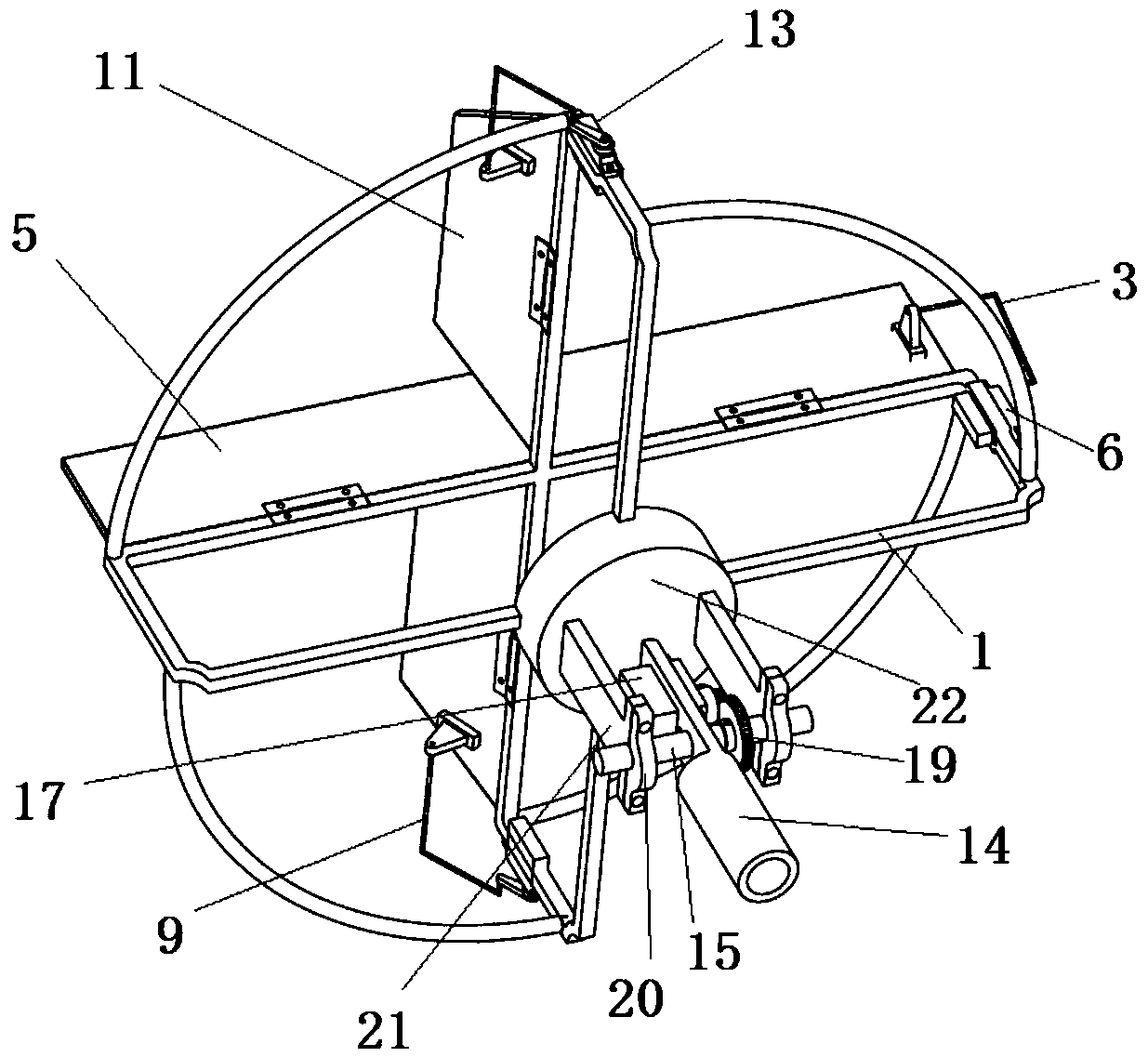
[0035]This embodiment is a tilting mechanism with a rudder surface, including a rudder surface mounting frame 1, a motor base 22, a horizontal rudder surface 5, two vertical rudder surfaces 11, a motor base 22, a tilting shaft 15, a connector and a Connect the mounting frame 14 of the fuselage. Wherein: the horizontal rudder surface 5 is installed on a long side of the horizontal rudder surface frame of the rudder surface installation frame 1 through a hinge, and the two vertical rudder surfaces 11 are respectively installed on the rudder surface installation through a hinge. One long side of the vertical rudder surface frame of the frame, and respectively located on the upper surface side and the lower surface side of the horizontal rudder surface. Both the horizontal rudder surface and the vertical rudder surface are on the same side of the rudder surface installation frame. The motor base 22 is located on the other side of the control surface mounting frame, and is fixed a...


PUM


Abstract

The invention provides a tilting mechanism with a control surface. A horizontal control surface is mounted on a long side of a horizontal control surface frame; and two vertical control surfaces are correspondingly mounted on one long side of a vertical control surface frame. The horizontal control surface and the vertical control surfaces are all positioned on the same side of a control surface mounting frame. A motor is fixed at a cross-shaped center formed by the horizontal control surface frame and the vertical control surface frame. Two ends of a tilting shaft are correspondingly fixed between an upper connecting piece and a lower connecting piece. A horizontal control surface steering engine is mounted at one end of the horizontal control surface frame of the control surface mountingframe; and vertical control surface steering engines are correspondingly mounted at the two ends of the vertical control surface frame of the control surface mounting frame. According to the tiltingmechanism with the control surface, by using the attached control surface, the tilting mechanism can self-balance moment, the resisting ability to outside airflow interference is higher, and the desired mounting accuracy is lower; the attitude can be more easily controlled in a vertical take-off and landing state or a lower flying speed state; the tension of a rotor is 10.13 N under conditions ofno aircraft body shielding and 9000 revolutions per minute; and the aerodynamic efficiency is enhanced.

Description

technical field [0001] The invention relates to the field of aircraft, in particular to a tilting mechanism with a rudder surface. Background technique [0002] A tilt-rotor aircraft is an aircraft capable of vertical take-off and landing, hovering in the air, and high-speed cruising flight. The rotors provide lift for the aircraft during vertical take-off and landing and hovering in the air. In level flight, the rotor provides forward pull. Tilting mechanism is exactly the mechanism that realizes two kinds of state switching. [0003] Existing typical patents for tilting mechanisms, such as Publication No. CN105620743A "A Tilting Mechanism for a Tilting Three-rotor Aircraft", adopts the rotor layout of "two fronts and one rear", but it has the following problems: 1. When the rear rotor rotates, the motor It will generate anti-torque on the fuselage, leading to changes in the attitude of the aircraft and affecting flight safety. 2. Due to the low speed of the aircraft du...

Claims


Application Information

Patent Timeline
Patent Type & Authority Applications(China)
IPC IPC(8): B64C27/52
CPCB64C27/52
Inventor 桑晓庆韩庆秦琪邵金石柳司方
Owner NORTHWESTERN POLYTECHNICAL UNIV
Why Eureka
Try Eureka