Eureka AIR delivers breakthrough ideas for toughest innovation challenges, trusted by R&D personnel around the world.

Rail deformation control structure in high-speed railway tunnel passing through large movable fault

A technology for high-speed railways and active faults, applied in tracks, tunnels, tunnel linings, etc., can solve problems such as increased project investment costs, huge excavation, and increased construction costs, improve structural safety and stability, and ensure operation. Safety and the effect of improving service life

Pending Publication Date: 2019-02-22
CHINA RAILWAY SIYUAN SURVEY & DESIGN GRP
View PDF0 Cites 5 Cited by
  • Summary
  • Abstract
  • Description
  • Claims
  • Application Information

AI Technical Summary

Problems solved by technology

At present, the commonly used treatment methods are as follows: 1. Set a flexible joint structure at the interface between soil and rock, such as a large deformation ring. This flexible structure allows the lining connected at both ends to be stretched, compressed and sheared within a certain range. In order to reduce the seismic response of the remaining sections of the tunnel, this method is suitable for the case where the span between the soft and hard junctions is small, otherwise the seismic effect will be greatly reduced due to the limited length of the deformation ring; 2. Cross-section expansion, through cross-section expansion in the weak broken zone or soft and hard sudden changes, directly increases the reserved space between the lining structure of the expansion section and other section structures. This method allows the lining structure of the expansion section to withstand earthquakes. However, this method is only suitable for fault zones with small spans. If large-scale active fault zones are crossed, huge excavation will occur in the expanded tunnel section. , and cause a significant increase in project cost, and when the earthquake is strong, due to the large difference between the stiffness of the tunnel structure and the surrounding rock, the tunnel structure is more prone to structural damage; 3. Set up a shock-absorbing layer for the tunnel structure
Usually, the shear modulus of the shock-absorbing layer is low. When an earthquake occurs, the surrounding rock moves, and the shift deformation transmitted to the tunnel structure through the shock-absorbing layer is reduced, so as to achieve the purpose of shock absorption. However, due to the laying of shock-absorbing Layer materials increase the project investment cost, and are generally suitable for areas with small spans of active fault zones. If the span of active fault zones is large, the construction cost will be greatly increased
[0005] In addition, although the setting of the flexible joint structure can solve the structural stability problem of the tunnel crossing large-scale active faults to a certain extent, since the track in the tunnel is often integrated with the tunnel through the track slab and concrete pouring, once an earthquake occurs, the tunnel When the structure is displaced, the track will be staggered together, causing serious distortion of the track; in addition, the high-speed railway has a high traffic density (generally every 5 minutes in one direction), high speed, and long braking distance. The train happened to pass through this section when the incident occurred. Even if the train took emergency braking measures in advance, the train is very likely to derail. In severe cases, it may even cause the train to overturn and hit the tunnel wall, causing damage to the tunnel structure and causing more serious accidents. secondary disaster
Therefore, the existing tunnel structures that cross large-scale active faults cannot fully meet the safety and stability of the tunnel in this section, and there are certain limitations

Method used


Image

  • Rail deformation control structure in high-speed railway tunnel passing through large movable fault
  • Rail deformation control structure in high-speed railway tunnel passing through large movable fault
  • Rail deformation control structure in high-speed railway tunnel passing through large movable fault

Examples


Embodiment Construction

[0036] In order to make the object, technical solution and advantages of the present invention clearer, the present invention will be further described in detail below in conjunction with the accompanying drawings and embodiments. It should be understood that the specific embodiments described here are only used to explain the present invention, not to limit the present invention.

[0037] In addition, the technical features involved in the various embodiments of the present invention described below can be combined with each other as long as they do not constitute a conflict with each other.

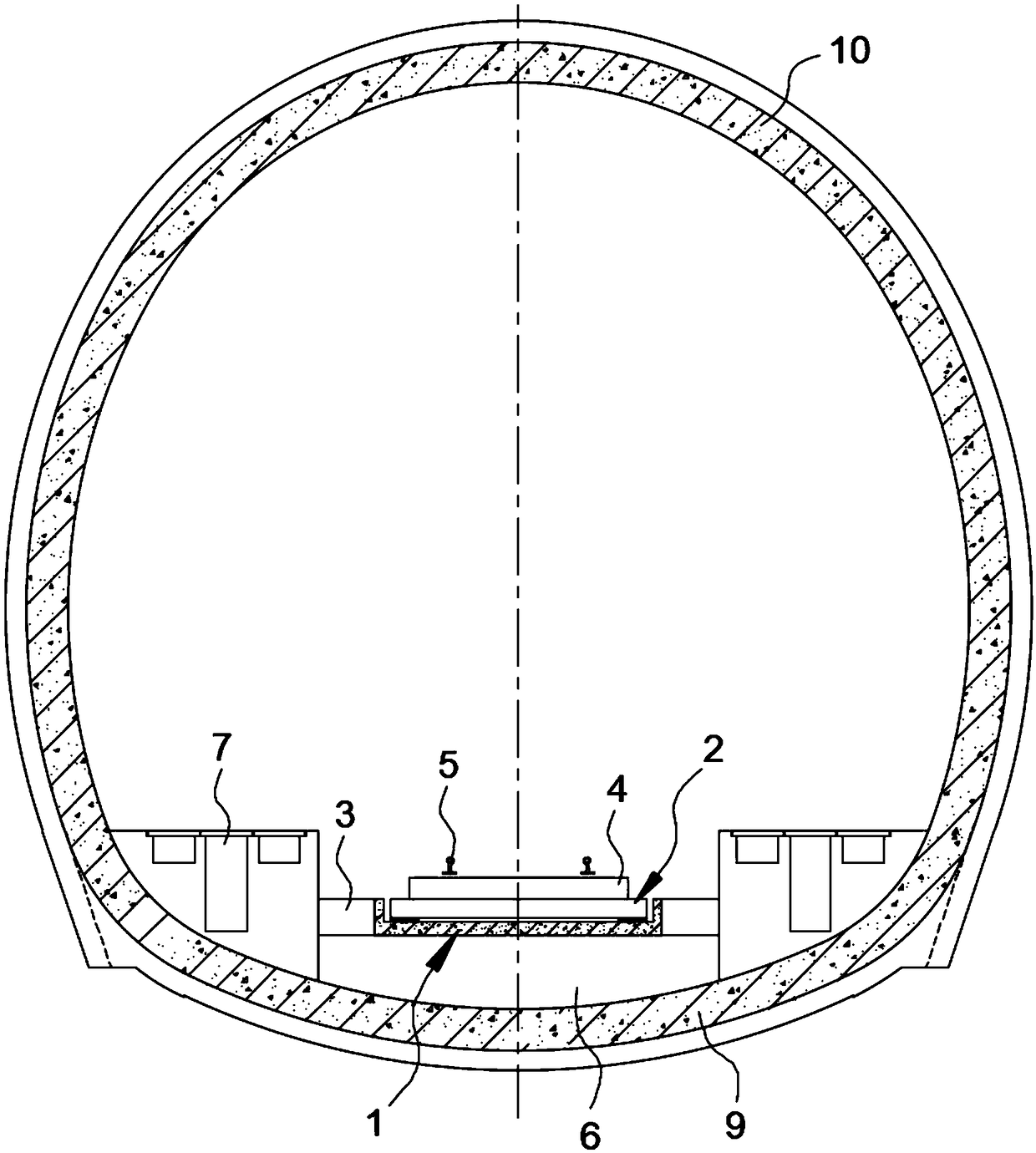
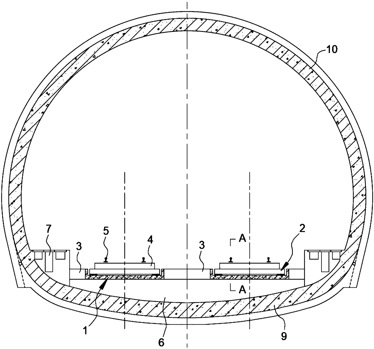
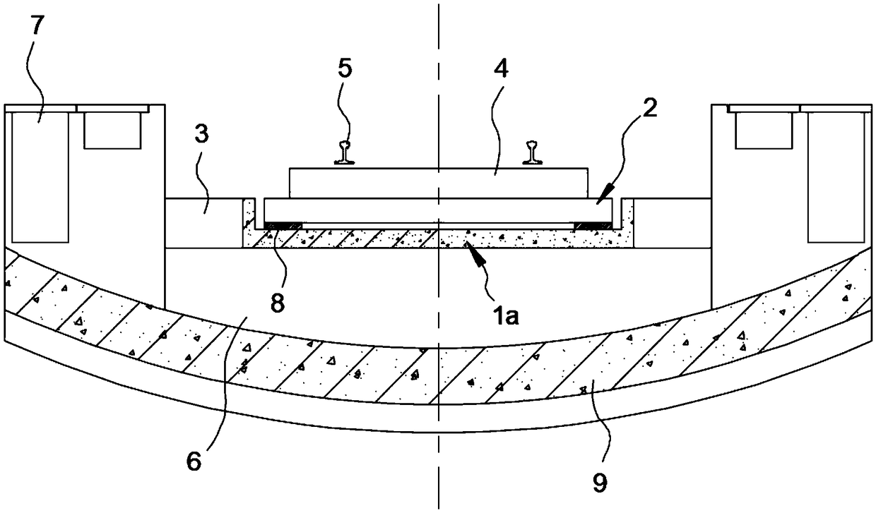
[0038] In the preferred embodiment of the present invention, the track deformation control structure in the high-speed railway tunnel crossing large-scale active faults is as follows: figure 1 As shown in this figure, the track deformation control structure in a single-track tunnel is shown in this figure. If the tunnel is a double-track tunnel, the structural diagram is as follows fi...


PUM


Abstract

The invention discloses a rail deformation control structure in a high-speed railway tunnel passing through a large movable fault, and belongs to the technical field of high-speed railway tunnel engineering. The height of an inverted arch filling layer in the high-speed railway tunnel passing through the large movable fault is preferentially set; and a buttress, a bracket and a longitudinal beam are correspondingly arranged between a rail plate and the inverted arch filling layer to form the rail deformation control structure, so that the longitudinal beam, the rail plate and a steel rail cannot transversely swing along with the inverted arch filling layer under the earthquake effect to realize safe operation of the rail structure in the high-speed railway tunnel passing through the largemovable fault under the earthquake effect. The rail deformation control structure is simple in structure and lower in setting cost, can effectively guarantee normal operation of the rail structure inthe high-speed railway tunnel when crossing through the large movable fault section, reduces the deformation of the rail structure under the earthquake effect, guarantees the operation safety and stability of the high-speed railway tunnel, and achieves excellent popularization and application value.

Description

technical field [0001] The invention belongs to the technical field of high-speed railway tunnel engineering, and in particular relates to a track deformation control structure in a high-speed railway tunnel crossing large-scale active faults. Background technique [0002] With the continuous development of my country's railway construction, especially the large-scale construction of high-speed railways, the number of applications of railway tunnels is increasing. In the construction of tunnel engineering, it is inevitable to pass through strong earthquake areas or fault fracture zones. Since the repair of underground structures damaged by earthquakes is extremely difficult and the repair cost is high, the seismic research on underground structures is especially important. It is very necessary to study the seismic resistance of tunnels in high-intensity earthquake areas. [0003] When the tunnel crosses an active fault, especially in the area of ​​the weak fracture zone, du...

Claims


Application Information

Patent Timeline
IPC IPC(8): E01B13/02E01B1/00E21D11/00E21F16/02
CPCE21D11/00E21F16/02E01B1/00E01B13/02
Inventor 肖明清王少锋龚彦峰邓朝辉周坤徐晨
Owner CHINA RAILWAY SIYUAN SURVEY & DESIGN GRP
Why Eureka
Eureka Blog
Learn More