
Heat accumulating type heating furnace

A heating furnace and regenerative technology, applied in the field of heating furnace, can solve problems such as instability, achieve the effects of avoiding pollution, uniform heating, and improving combustion rate

Inactive Publication Date: 2019-02-22
张淑芳
View PDF9 Cites 0 Cited by
  • Summary
  • Abstract
  • Description
  • Claims
  • Application Information

AI Technical Summary

Problems solved by technology

[0002] Regenerative heat exchange technology, which belongs to unsteady state heat transfer, uses refractory material as carrier, is alternately heated by exhaust gas heat, and then heats air or gas with the heat stored in the regenerator, so that air and gas can be preheated at high temperature, To achieve the efficiency of waste heat recovery, since the regenerator is periodically heated and released, in order to ensure the continuity of the furnace heating, the regenerator must be set in pairs. The high-efficiency regenerative combustion system of the regenerative heating furnace is mainly composed of Composed of thermal burner and reversing system, it is divided into three main parts: preheating section, heating section and soaking section. Damp heat, the effect of increasing the temperature of the combustion-supporting air, the main on-site equipment involved in the control of the heating furnace are: thermocouples for measuring the furnace temperature of each section, thermocouples for measuring the safety of flue gas before and after the gas heater, and the inlet of the fan for air quality adjustment of the regenerative heating furnace Air inlet valve, gas main cut-off valve and pressure regulating valve, other safety protection chain equipment, etc., but there is no automatic feeding of heat storage type heating furnace, and waste residue and waste gas are discharged directly without inspection

Method used


Image

  • Heat accumulating type heating furnace
  • Heat accumulating type heating furnace
  • Heat accumulating type heating furnace

Examples


Embodiment Construction

[0015] The following will clearly and completely describe the technical solutions in the embodiments of the present invention with reference to the accompanying drawings in the embodiments of the present invention. Obviously, the described embodiments are only some, not all, embodiments of the present invention. Based on the embodiments of the present invention, all other embodiments obtained by persons of ordinary skill in the art without making creative efforts belong to the protection scope of the present invention.

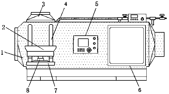
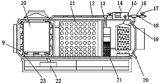
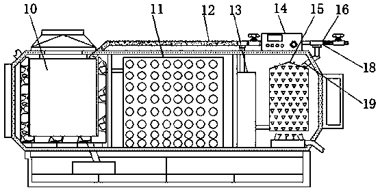
[0016] see Figure 1-3 , an embodiment provided by the present invention: a regenerative heating furnace, including a furnace body 1, a feeding shell 2, a slide rail 4, a control panel 5 and a transparent window 6, installed at the center of the surface of the furnace body 1 There is a control panel 5, the surface of the furnace body on one side of the control panel 5 is fixed with a transparent window 6, the side of the control panel 5 away from the transpare...


PUM


Abstract

The invention discloses a heat accumulating type heating furnace. The heating furnace comprises a furnace body, a feeding shell, a sliding rail, a control panel and a transparent window, a control panel is arranged at the center position of the surface of the furnace body, the transparent window is fixed on the surface of the furnace body on one side of the control panel, far away from the transparent window, of the control panel is provided with the feeding shell, a supporting disc is fixed on the surface of the furnace body below the feeding shell, an air cylinder is installed at the centerof the top end of the supporting disc, sliding rails are arranged on the two sides above the supporting disc, a combustion chamber is arranged at one end inside the furnace body, a water bath heatingtube is arranged at the center position inside the combustion chamber, a combustion cylinder is installed on the inner side of the water bath heating tube, close to one side of the box body, of the furnace body is provided with a gas detector, an output end of the gas detector is provided with a gas conveying pipe through a guide pipe. According to the heat accumulating type heating furnace, the working efficiency of the heating furnace is improved, the combustion rate of the fuel is improved, and the filtering and detecting functions of the waste gas are realized.

Description

technical field [0001] The invention relates to the technical field of heating furnaces, in particular to a regenerative heating furnace. Background technique [0002] Regenerative heat exchange technology, which belongs to unsteady state heat transfer, uses refractory material as carrier, is alternately heated by exhaust gas heat, and then heats air or gas with the heat stored in the regenerator, so that air and gas can be preheated at high temperature, To achieve the efficiency of waste heat recovery, since the regenerator is periodically heated and released, in order to ensure the continuity of the furnace heating, the regenerator must be set in pairs. The high-efficiency regenerative combustion system of the regenerative heating furnace is mainly composed of Composed of thermal burner and reversing system, it is divided into three main parts: preheating section, heating section and soaking section. Damp heat, the effect of increasing the temperature of the combustion-su...

Claims


Application Information

Patent Timeline
Patent Type & Authority Applications(China)
IPC IPC(8): F27B17/00F27D17/00
CPCF27B17/00F27D17/008
Inventor 张淑芳
Owner 张淑芳
Learn More