Fault traveling wave signal coupling sensor for online fault ranging device

A fault traveling wave and signal coupling technology, which is applied in the field of sensors, can solve problems such as being susceptible to interference, low test accuracy, and distance measurement errors ranging from hundreds of meters to several kilometers, so as to shield stray signal interference and improve power supply The effect of reliability and good market application value

Pending Publication Date: 2019-02-22
GUANGDONG POWER GRID CO LTD +1
View PDF0 Cites 2 Cited by
  • Summary
  • Abstract
  • Description
  • Claims
  • Application Information

AI Technical Summary

Problems solved by technology

This method has the following problems in the application of long-distance submarine cables: the time resolution of GPS is more than a few microseconds, the ranging error is more than a few hundred meters to several kilometers, and the test accuracy is low; the cost is high; Acquisition of fault traveling wave signal has poor waveform and is susceptible to interference; the reliability of the electrical connection between voltage sensor and high voltage is poor, and capacitive sensor is not suitable for long lines
For tens or even hundreds of kilometers of long-distance submarine cable lines, when the fault point is close to one of the terminals, due to the attenuation of the fault traveling wave signal along the cable, the sensitivity of the conventional sensor signal is low. At this time, the sensor of the other terminal detects The fault traveling wave signal is not available, resulting in the failure of the online ranging function

Method used


Image

  • Fault traveling wave signal coupling sensor for online fault ranging device
  • Fault traveling wave signal coupling sensor for online fault ranging device
  • Fault traveling wave signal coupling sensor for online fault ranging device

Examples


Embodiment 1

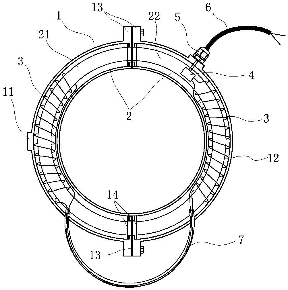
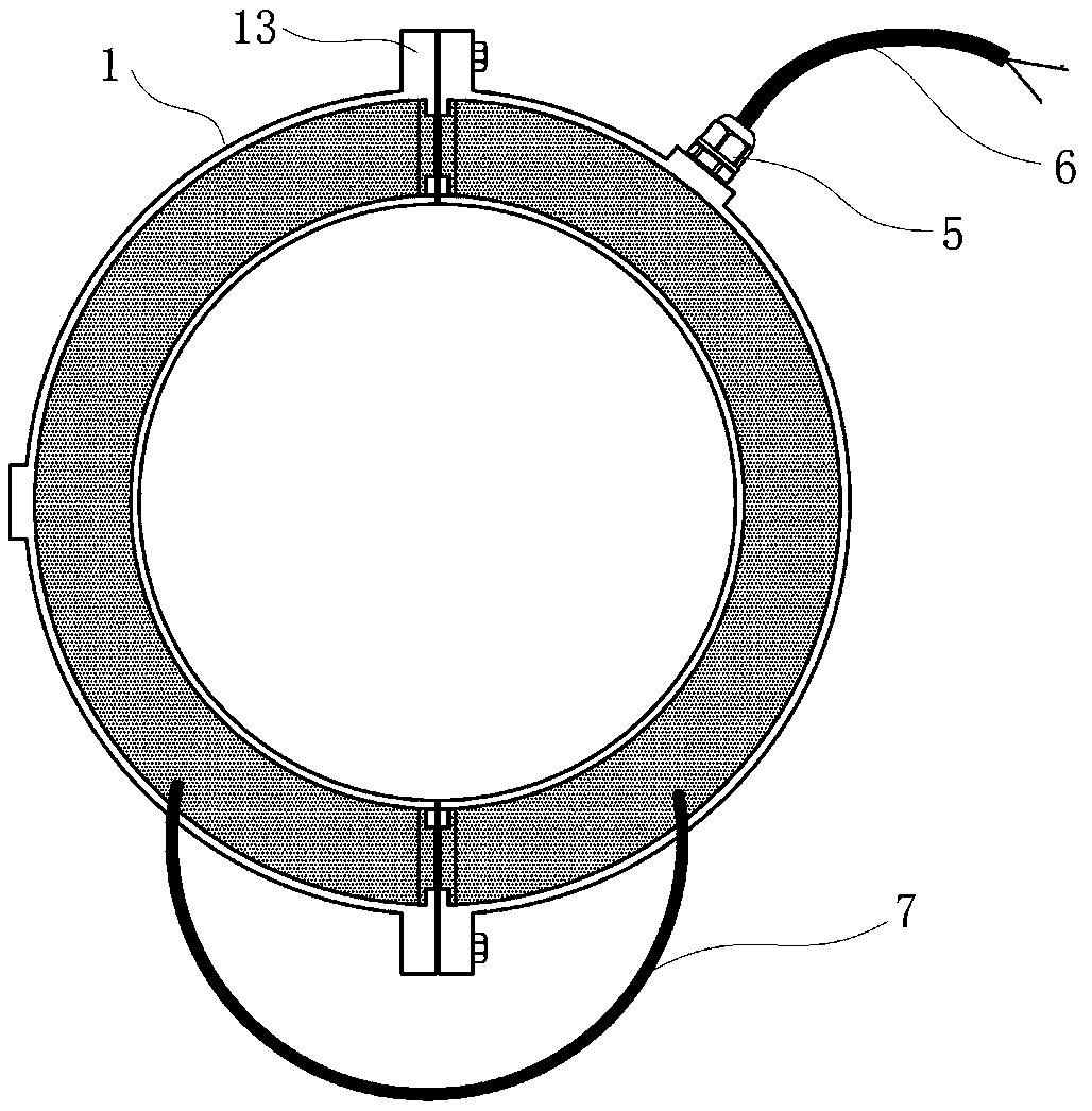
[0024] like Figure 1 to Figure 3 As shown, a fault traveling wave signal coupling sensor for an online fault distance measuring device includes a housing 1, a winding frame 2, a coil 3, a signal board 4, a PG head 5 and a signal line 6, and the winding Skeleton 2 is set in casing 1, said coil 3 is wound on winding bobbin 2, said signal board 4 is fixed in casing 1, coil 3 is electrically connected with signal board 4, on casing 1 A mounting hole is provided, and the PG head 5 is connected to the mounting hole. The signal line 6 passes through the PG head 5 and is connected to the signal board 4 , and the signal line 6 is fixed on the housing 1 through the PG head 5 .

[0025] In the present invention, the sensor has a built-in frequency selection and protection circuit, and a symmetrical coil 3 winding structure on both sides ensures effective signal pickup. Based on traveling wave transmission theory, transformer principle, parallel resonance technology and mold technology,...

Embodiment 2

[0034] This embodiment is similar in structure to other parts of Embodiment 1, the difference is that both ends of the first semi-annular shell 11 and the second semi-annular shell 12 are provided with baffles 14 for sealing, and the casing 1 is filled with There is insulation. Insulation impregnated to keep out moisture and improve insulation performance. Setting the baffle plate 14 to seal can prevent the material from overflowing when pouring the insulating material.


PUM


Abstract

The present invention relates to the technical field of sensors and more particularly relates to a fault traveling wave signal coupling sensor for an online fault ranging device. The sensor includes ahousing, a wire winding framework, a coil, a signal board, a PG head, and a signal line. The wire winding framework is arranged in the housing, the coil is wound on the wire winding framework, the signal board is fixed in the housing, the coil is electrically connected to the signal board, a mounting hole is formed in the housing, the PG head is connected to the mounting hole, the signal line passes through the PG head to connect the signal board, and the signal line is fixed to the housing through the PG head. The fault traveling wave signal coupling sensor for the online fault ranging device provided by the invention has good market application value for ensuring the effectiveness of the online fault positioning device and improving the power supply reliability of a power grid.

Description

technical field [0001] The invention relates to the technical field of sensors, and more specifically, to a fault traveling wave signal coupling sensor used for an online fault distance measuring device. Background technique [0002] Submarine cables are an important part of the construction of cross-sea networking projects, and play an important role in realizing the internationalization of power grids and the interconnection of regional power grids. In recent years, with the improvement of the economic level, the demand for electric energy on various islands and land is increasing. Many areas of the national power grid have built and are building a large number of submarine cables and offshore wind power, such as Jiangmen, Zhanjiang, Zhuhai, Shantou, Zhoushan and other islands. submarine cables. [0003] However, in terms of submarine cable operation and maintenance, high-precision monitoring and detection of submarine cables, as well as early warning of fault locations a...

Claims


Application Information

Patent Timeline
Patent Type & Authority Applications(China)
IPC IPC(8): G01R31/08
CPCG01R31/083Y04S10/52
Inventor 孙廷玺王升黄毓华李辰周锋李鹏崔江静仇炜郭小凯方义治郑柒拾张宽锋丁鹏
Owner GUANGDONG POWER GRID CO LTD
Why Eureka
Try Eureka