Eureka AIR delivers breakthrough ideas for toughest innovation challenges, trusted by R&D personnel around the world.

Self-diagnosis alarm device and method of optical path fault for optical fiber current transformer

An optical fiber current and alarm device technology, applied in the field of electric power, can solve the problems of misoperation of relay protection devices, inability to accurately determine the optical path fault position of fiber optic current transformers, and overdiagnosis.

Active Publication Date: 2019-02-22
ELECTRIC POWER RES INST OF EAST INNER MONGOLIA ELECTRIC POWER +3
View PDF8 Cites 10 Cited by
  • Summary
  • Abstract
  • Description
  • Claims
  • Application Information

AI Technical Summary

Problems solved by technology

Smart substations have extremely high requirements for the reliability and intelligence of optical fiber current transformers. It is required that optical fiber current transformers should send out early warning and maintenance signals when their performance deteriorates, and can perform self-diagnosis and give alarm information in time when a fault occurs. Avoid quality failure of the equipment itself, send wrong measurement data, cause misoperation and power failure of the relay protection device at the back end of the power system
[0005] To sum up, the fiber optic current transformer needs a complete optical path self-diagnosis function. At present, the optical path alarm function of the fiber optic current transformer can basically diagnose the fault of the optical path. However, the fault diagnosis data information is limited. In order to ensure the reliability of the equipment, the fiber optic current transformer The self-diagnosis design of the fiber optic current transformer is relatively strict, and over-diagnosis often occurs, resulting in normal equipment shutdown and repair. When the fiber optic current transformer fails, it is impossible to accurately determine the fault location of the optical path of the fiber optic current transformer

Method used


Image

  • Self-diagnosis alarm device and method of optical path fault for optical fiber current transformer
  • Self-diagnosis alarm device and method of optical path fault for optical fiber current transformer
  • Self-diagnosis alarm device and method of optical path fault for optical fiber current transformer

Examples


Embodiment Construction

[0066] It should be pointed out that the following detailed description is exemplary and intended to provide further explanation to the present application. Unless defined otherwise, all technical and scientific terms used herein have the same meaning as commonly understood by one of ordinary skill in the art to which this application belongs.

[0067] It should be noted that the terminology used here is only for describing specific implementations, and is not intended to limit the exemplary implementations according to the present application. As used herein, unless the context clearly dictates otherwise, the singular is intended to include the plural, and it should also be understood that when the terms "comprising" and / or "comprising" are used in this specification, they mean There are features, steps, operations, means, components and / or combinations thereof.

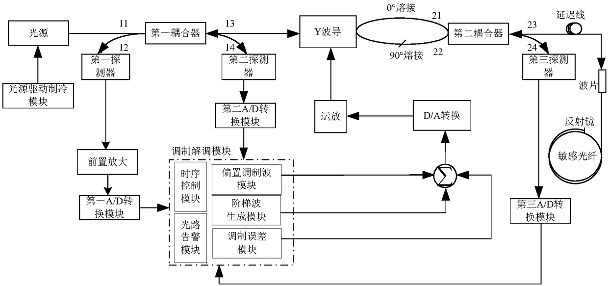
[0068] figure 1 It is a structural schematic diagram of an optical path fault self-diagnosis and alarm device f...


PUM


Abstract

The invention discloses a self-diagnosis alarm device and method of an optical path fault for an optical fiber current transformer. The device comprises a first coupler; a first port, a second port, athird port and a fourth port of the first coupler are connected with a light source, a first detector, a Y waveguide and a second detector correspondingly and respectively; the Y waveguide is furtherconnected to a third detector and a lambda / four wave plate through a second coupler; and the first detector, the second detector, and the third detector are connected to a modem module. Light entering the lambda / four wave plate through the second coupler is transformed into two beams of circularly polarized light and then the two beams of circularly polarized light enters a sensitive fiber directly; after the sensitive fiber transmits the light to a reflecting mirror, the light is reflected and then passes through the sensitive fiber and the lambda / four wave plate successively and then returns to the Y waveguide to form interference light; the interference light is transmitted to the modem module through the first coupler and the first detector successively; and the modem module is connected with the Y waveguide to realize closed-loop controlling.

Description

technical field [0001] The invention belongs to the field of electric power, and in particular relates to an optical path fault self-diagnosis alarm device and method for an optical fiber current transformer. Background technique [0002] As a new type of current measuring equipment, the fiber optic current transformer has the advantages of simple insulation, small size, safety and reliability, digitalization, metering, measurement, and protection integration. It is the key equipment for the construction of smart substations. The research and development of fiber optic current transformers started earlier in foreign countries, and they were also the first to carry out network operation. The research and development of optical fiber current transformers in my country started relatively late, but it has developed rapidly and the technical level has improved greatly. In recent years, especially driven by the demand for intelligent substation construction, the market demand for ...

Claims


Application Information

Patent Timeline
IPC IPC(8): G01R35/02
CPCG01R35/02
Inventor 钱文晓司磊郭金刚石海鹏肖冰王利清林海丹靳俊杰敖明杨明
Owner ELECTRIC POWER RES INST OF EAST INNER MONGOLIA ELECTRIC POWER
Why Eureka
Eureka Blog
Learn More