Net belt type sintering furnace

A sintering furnace, mesh belt type technology, applied in the furnace, charge, furnace components and other directions, can solve the problems of difficult control, large temperature fluctuation, affecting the sintering quality, etc., to avoid temperature channeling, avoid the effect of different tightness

Pending Publication Date: 2019-02-26
黄翔鸥
View PDF7 Cites 0 Cited by
  • Summary
  • Abstract
  • Description
  • Claims
  • Application Information

AI Technical Summary

Problems solved by technology

The workpieces generally include the following steps when they are coated with Dacromet or Jiumet, degreasing treatment, shot blasting, dipping coating, and then sending the coated bolts to the sintering furnace for baking and drying. The coating is sintered and solidified; the heating area of ​​the existing sintering furnace is generally divided into a preheating section, a sintering section and a cooling section. The furnace body of the three sections is a continuous design, and the end of the preheating section is connected to the front end of the sintering section , the tail end of the sintering section is connected to the front end of the cooling section, which makes the interaction between the preheating section and the sintering section, and between the sintering section and the cooling section, resulting in large temperature fluctuations at both ends of the sintering section, which is difficult to control and affects sintering quality

Method used


Image

  • Net belt type sintering furnace
  • Net belt type sintering furnace
  • Net belt type sintering furnace

Examples


Embodiment 1

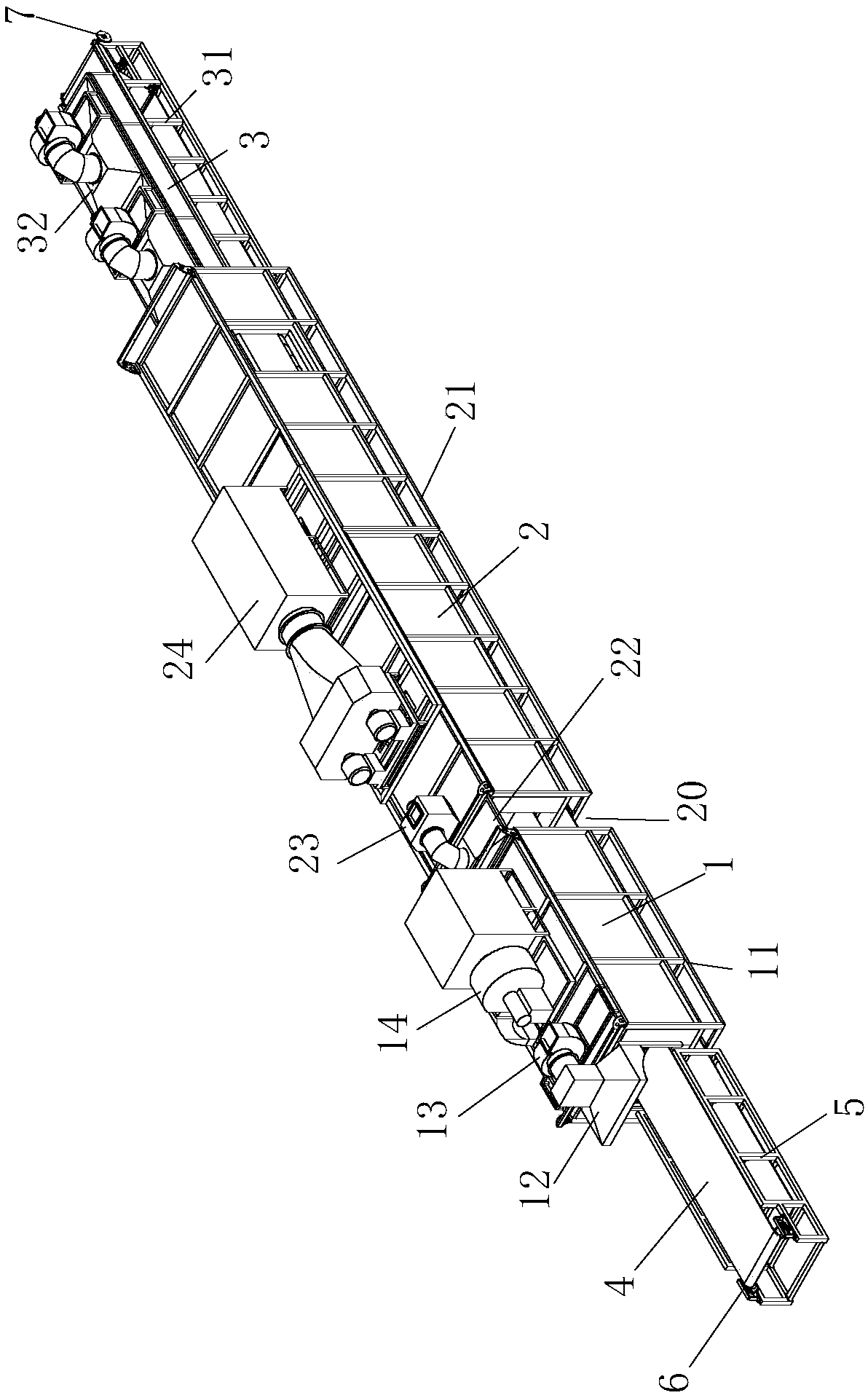
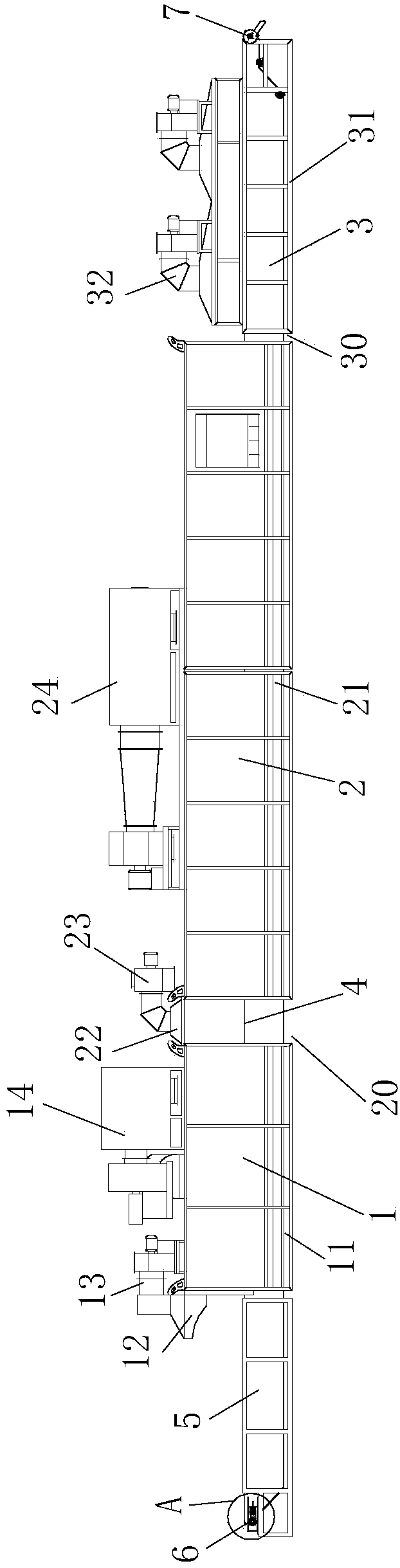
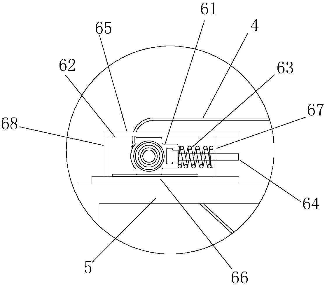
[0015] Example 1 as Figure 1 to Figure 2 As shown, the mesh belt sintering furnace of this embodiment includes a preheating section furnace body 1, a sintering section furnace body 2 and a cooling section furnace body 3, the preheating section furnace body 1 is arranged in the preheating section frame 11, and the sintering section furnace The body 2 is arranged in the frame 21 of the sintering section, the furnace body 3 of the cooling section is arranged in the frame 31 of the cooling section, and the front end of the furnace body 1 of the preheating section is provided with a frame 5 of the feeding section, the frame 5 of the feeding section, the furnace body of the preheating section 1. The furnace body 2 of the sintering section and the furnace body 3 of the cooling section are placed on the same straight line; the front end of the feeding section frame 5 is provided with a passive roller assembly 6, the rear end of the cooling section frame 31 is provided with a driving r...


PUM


Abstract

The invention relates to a net belt type sintering furnace. The net belt type sintering furnace comprises a preheating section furnace body, a sintering section furnace body and a cooling section furnace body which are arranged on the same straight line; the sintering furnace further comprises a preheating section furnace body, a sintering section furnace body and a conveying net belt inside the cooling section furnace body which penetrate through the front and back parts, heating systems are arranged inside the preheating section furnace body and the sintering section furnace body respectively, and a cooling system is arranged inside the cooling section. The sintering furnace is characterized in that the tail end of the preheating section furnace body and the front end of the sintering section furnace body are arranged in a spaced mode, and the tail end of the sintering section durance body and the front end of the cooling section furnace body are arranged in a spaced mode so that thepreheating section and the sintering section do not affect each other and the sintering section and the cooling section do not affect each other.

Description

technical field [0001] The invention relates to the technical field of Dacromet sintering equipment, in particular to a mesh-belt sintering furnace. Background technique [0002] Dacromet and Jiumet are the best technologies to replace the traditional electro-galvanizing and hot-dip galvanizing which have serious environmental pollution. It can not only process steel, iron, aluminum and its alloys, iron castings, structural parts, but also sintered metals and special surface treatment. Widely used in automobiles, motorcycles, transportation facilities industries (metal parts of high-speed railways, subways, electrified railways, tunnels, bridge viaducts, and metal parts of expressways), electrical appliances, ships, aerospace, marine engineering, hardware tools, electric power, Communication, petrochemical, gas engineering, construction, military products, household appliances and other industries. It not only improves product quality, but also protects the natural ecologi...

Claims


Application Information

Patent Timeline
Patent Type & Authority Applications(China)
IPC IPC(8): F27B9/24F27B9/30F27B9/36F27D3/12F27D17/00F27D99/00B05D3/02
CPCF27B9/243F27B9/30F27B9/36F27D3/12F27D17/004F27D99/007B05D3/0272F27M2003/04F27D2003/121F27B2009/3088F27B2009/3607F27B2009/2446
Inventor 黄翔鸥张中敏
Owner 黄翔鸥
Why Eureka
Try Eureka