
Laser ultrasonic detection device and additive manufacturing and detection integrated equipment

A technology of laser ultrasonic and detection device, applied in the field of additive manufacturing, can solve the problem that the positioning accuracy needs to be further improved or not considered, and achieve the effect of improving the effect, improving the accuracy and improving the pass rate

Pending Publication Date: 2019-02-26
NAT INST CORP OF ADDITIVE MFG XIAN
View PDF2 Cites 17 Cited by
  • Summary
  • Abstract
  • Description
  • Claims
  • Application Information

AI Technical Summary

Problems solved by technology

However, the method and device do not consider the influence of the temperature of the workpiece on the wave velocity of the ultrasonic signal during the additive manufacturing process, and the accuracy of defect positioning needs to be further improved.

Method used


Image

  • Laser ultrasonic detection device and additive manufacturing and detection integrated equipment
  • Laser ultrasonic detection device and additive manufacturing and detection integrated equipment
  • Laser ultrasonic detection device and additive manufacturing and detection integrated equipment

Examples


Embodiment 1

[0041] Embodiment 1: laser ultrasonic detection device

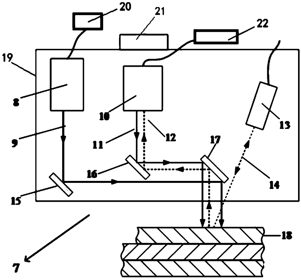
[0042] In order to improve the accuracy of non-destructive testing of internal defects of additive parts, the present invention provides a laser ultrasonic testing device, such as figure 1 As shown, it includes a laser ultrasonic detection probe 7, an excitation laser 20 and a laser ultrasonic receiver 22;

[0043] The laser ultrasonic detection probe 7 includes a housing 19, a focusing probe 8 arranged in the housing 19, a mirror 15, a receiving probe 10, a first lens 16, a second lens 17 and an infrared thermometer 13;

[0044] Wherein, the excitation laser 20 and the laser ultrasonic receiver 22 are arranged outside the housing; the laser ultrasonic receiver 22 includes a detection laser and a laser interferometer;

[0045] The focusing probe 8 is connected to an external excitation laser 20 through an optical fiber, and the receiving probe 10 is connected to an external laser ultrasonic receiver 22 through an optical...

Embodiment 2

[0050] Example 2: Integrated equipment for additive manufacturing and testing

[0051] The following is an introduction to the equipment from the three aspects of additive manufacturing, the mechanical structure of the detection integrated equipment, the control structure and the detection process:

[0052] mechanical structure

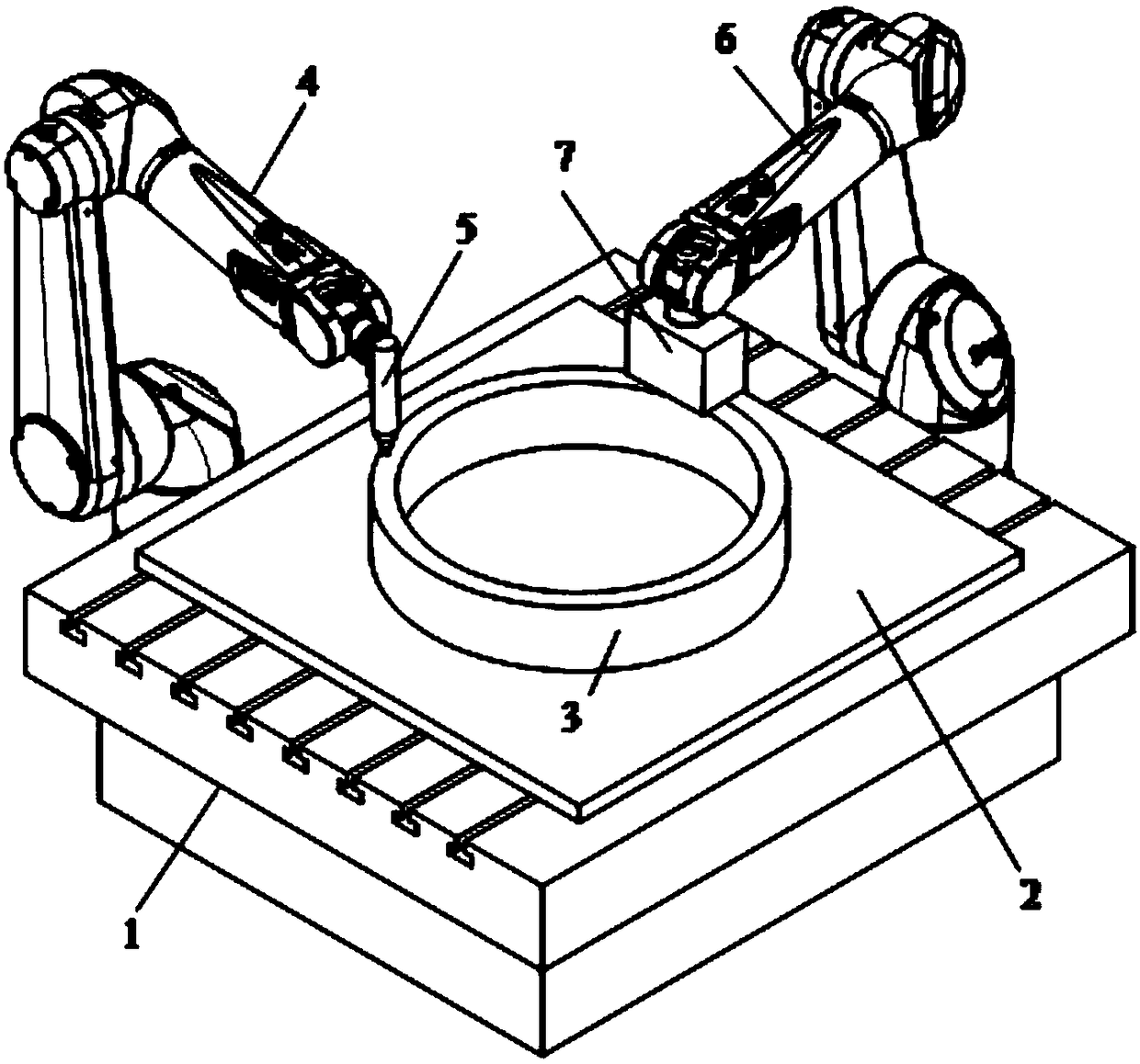
[0053] as attached figure 2 As shown, the equipment includes a first robot (in this embodiment, a welding robot 4), a second robot (in this embodiment, an industrial robot 6), a CMT welding torch 5, the laser ultrasonic testing device provided in Embodiment 1, Control unit and upper computer;

[0054] The workbench 1 is fixed on the ground, and the base plate 2 is fixed on the workbench 1 to form a work platform. The welding robot 4 is fixed on the ground or slide rails (not shown in the figure), and a CMT welding torch 5 is installed at the end. The welding robot 4 carries the CMT welding torch 5 to move, and accumulates and consolidates materials...


PUM


Abstract

The invention relates to a laser ultrasonic detection device and additive manufacturing and detection integrated equipment. The laser ultrasonic detection device comprises a laser ultrasonic detectionprobe, an excited laser and a laser ultrasonic receiver, wherein the laser ultrasonic detection probe comprises a casing, a focusing probe arranged in the casing, a reflector, a receiving probe, a first lens, a second lens and an infrared thermometer. The temperature of workpieces is detected by the infrared thermometer in real time while defects are detected by ultrasonic waves, so that the defect detection accuracy is improved substantially. Meanwhile, the laser ultrasonic detection device cooperates with an industrial robot, a welding robot and a welding gun to realize independent operation of detection and additive manufacturing, and mutual interference is avoided.

Description

technical field [0001] The invention belongs to the technical field of additive manufacturing, and in particular relates to a laser ultrasonic detection device and integrated equipment for additive manufacturing and detection. Background technique [0002] Additive manufacturing is a process based on three-dimensional model data, using a layer-by-layer stacking method opposite to subtractive manufacturing technology, and combining materials to produce products. It has high material utilization rate, short product manufacturing cycle, and complex structure integration. Manufacturing and other advantages, it has broad application prospects in aviation, aerospace, medical, construction machinery and other fields. [0003] However, defects will inevitably occur in the process of additive manufacturing, which seriously restricts the engineering application of additive parts in the above fields. Therefore, it is urgent to conduct non-destructive testing for internal defects of add...

Claims


Application Information

Patent Timeline
IPC IPC(8): G01N29/04
CPCG01N29/041G01N29/048G01N2291/023
Inventor 赵纪元王彪王琛玮卢秉恒
Owner NAT INST CORP OF ADDITIVE MFG XIAN
Learn More