Pneumatic friction nano-generator and sensor and sensing method in pneumatic system

A nano-generator and pneumatic system technology, applied in the field of sensors, can solve the problems of inability to monitor the working state, low integration, and complicated manufacturing process of the sensor working principle, and achieve the effect of simple structure, low cost and stable performance

Active Publication Date: 2019-02-26
BEIJING INST OF NANOENERGY & NANOSYST
View PDF4 Cites 6 Cited by
  • Summary
  • Abstract
  • Description
  • Claims
  • Application Information

AI Technical Summary

Problems solved by technology

[0003] On the other hand, pressure and flow sensors based on the principles of sound waves, piezoresistance, and electrostatic capacitance, and position detection sensors based on the Hall effect, which are widely used in pneumatic systems, have achieved some research results, but the working principles and fabrication of mos

Method used


Image

  • Pneumatic friction nano-generator and sensor and sensing method in pneumatic system
  • Pneumatic friction nano-generator and sensor and sensing method in pneumatic system
  • Pneumatic friction nano-generator and sensor and sensing method in pneumatic system

Examples


Example Embodiment

[0047] Example one:

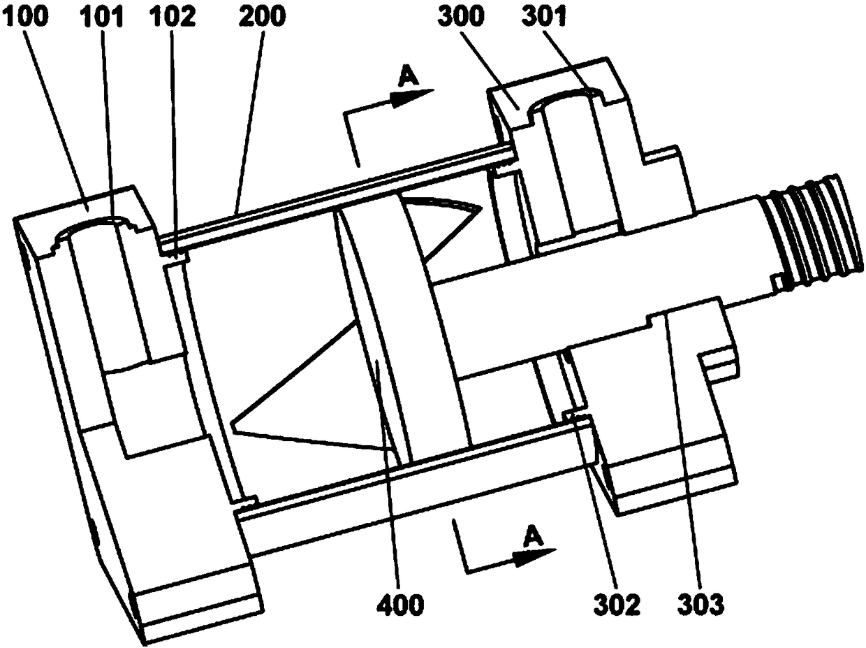
[0048] In this embodiment, a specific friction power generation component is taken as an example to introduce the pneumatic friction nano generator of the present invention in detail.

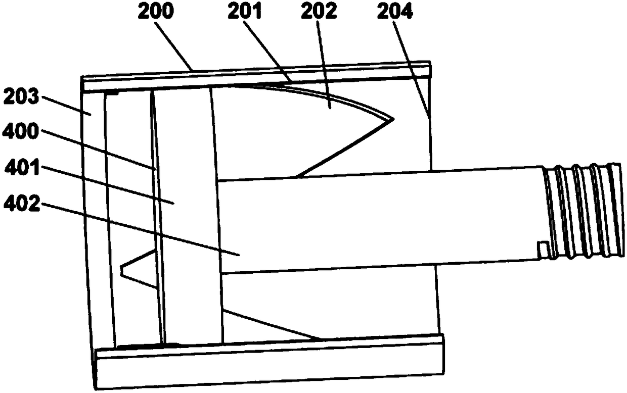
[0049] figure 1 It is a schematic cross-sectional view of the structure of the pneumatic friction nano-generator according to this embodiment. Such as figure 1 As shown, the pneumatic friction nano generator of the present invention includes a left end cover 100, a cylinder 200, a right end cover 300 and a piston 400. The left end cover 100 and the right end cover 300 are respectively screwed to the cylinder block 200, and the piston 400 is arranged inside the cylinder block 200 and can slide relative to the cylinder block 200. The side of the left end cover 100 is provided with a first air inlet 101. The compressed gas can enter the cylinder 200 from the first air inlet 101 and act on the left end surface of the piston 400 to cause the piston 400 to slide to the right; the le...

Example Embodiment

[0068] Embodiment two:

[0069] By detecting the electrical signal generated by the pneumatic friction nanogenerator in the first embodiment, it is also possible to detect the piston movement position, movement speed, gas pressure, flow rate and other parameters in the pneumatic system. Therefore, this embodiment provides a sensor in a pneumatic system.
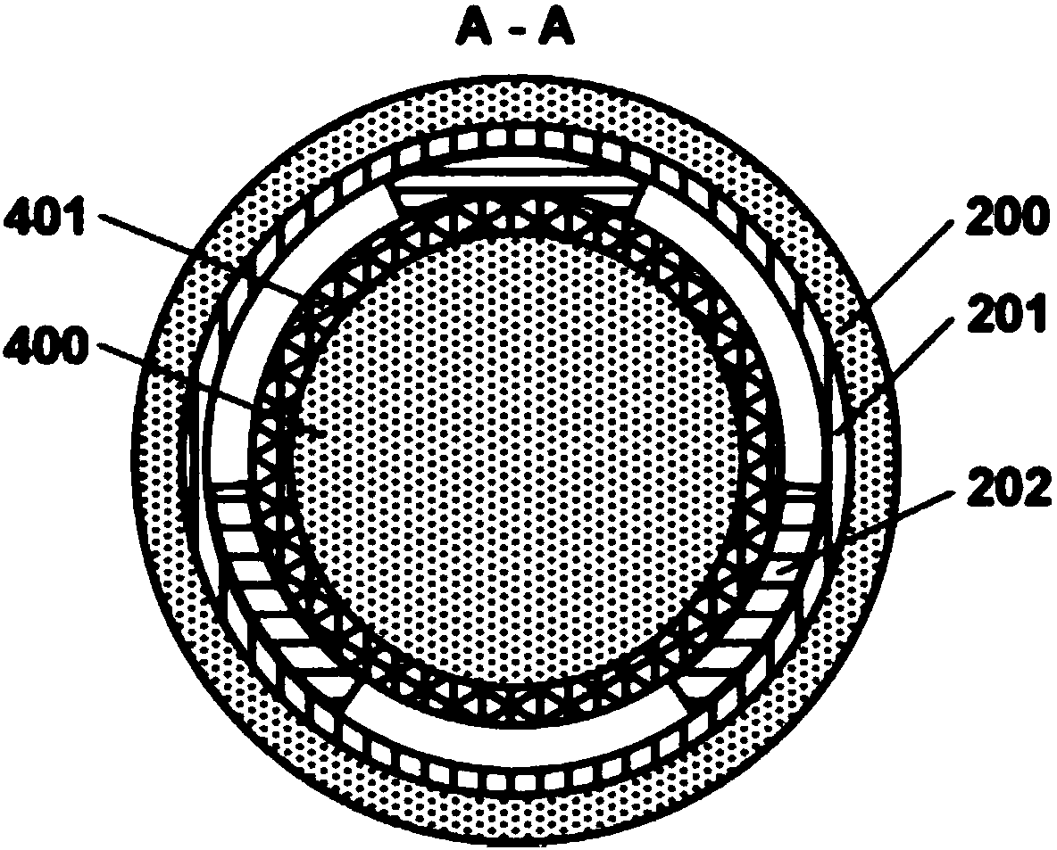
[0070] The following is an example of a conductive film with a triangular structure in the second friction layer (see Figure 1 to Figure 3 ), respectively describe the different sensing functions of the sensor in detail. The sensing process of sensors with other structures is similar, and will not be repeated here.


PUM


Abstract

The invention discloses a pneumatic friction nano-generator, and the nano-generator comprises a cylinder and a piston in a pneumatic system, and a friction generating component, wherein the piston isdisposed in the cylinder and is slidable relative to the cylinder. The friction generating component comprises a first friction layer and a second friction layer, which are respectively disposed on anouter side wall of the piston and an inner sidwall of the cylinder, and the material of the upper surface of the first friction layer and the material of the second friction layer have a frictional electronegativity difference. When the piston slides relative to the cylinder, the first friction layer and the second friction layer slide relative to each other and the contact area changes, and thefriction generating component generates an electrical signal. The invention also provides a sensor and sensing method in a pneumatic system. The generator of the invention can convert the pressure energy or mechanical energy generated by the fluid and a piston in the pneumatic system into electric energy, provides a continuous energy supply device for a low-power sensor in the pneumatic system, and can also be used as a self-driving sensor for monitoring the pneumatic system, wherein the continuous energy supply device can be used for monitoring the operating status of various functional components in the pneumatic system.

Description

technical field [0001] The invention relates to the technical field of friction power generation, in particular to a pneumatic friction nanogenerator, a sensor in a pneumatic system and a sensing method. Background technique [0002] With the continuous improvement of the intelligent level of the pneumatic system and its deep integration with Internet technology, a large number of low-power sensors are widely used in the pneumatic system to monitor the working status of various functional components in the pneumatic system. Stable and reliable continuous power supply to each sensor is the prerequisite to ensure its normal operation. However, the research on power supply systems matching these low-power sensors is relatively lagging behind. The current energy supply methods for low-power sensors in pneumatic systems mainly include direct power supply and chemical battery power supply. Among them, the direct power supply method has problems such as serious electromagnetic int...

Claims


Application Information

Patent Timeline
IPC IPC(8): H02N1/04G01D5/14B82Y15/00
CPCB82Y15/00G01D5/14H02N1/04
Inventor 张弛付贤鹏王中林程廷海
Owner BEIJING INST OF NANOENERGY & NANOSYST
Why Eureka
Try Eureka