Buried composite seepage pipe

A composite infiltration and buried technology, applied in watering devices, horticulture, botanical equipment and methods, etc., can solve the problems that the water seepage cannot be completely upward, affect the use effect, time-consuming and labor-intensive, etc., to overcome plant root blockage, The effect of high production efficiency and avoiding clogging

Pending Publication Date: 2019-03-01
河北广发农业科技有限公司
View PDF2 Cites 0 Cited by
  • Summary
  • Abstract
  • Description
  • Claims
  • Application Information

AI Technical Summary

Problems solved by technology

[0005] The current seepage pipes are usually produced and sold by manufacturers in the form of fixed lengths. When farmers or farms use them, they are connected according to their needs, and open trenches are dug and laid, which is time-consuming and laborious.
At the same time, when the seepage pipe is under the action of external force, because there is no positioning device, the seepage opening cannot be completely upward, which has a certain randomness and directly affects the use effect

Method used


Image

  • Buried composite seepage pipe
  • Buried composite seepage pipe
  • Buried composite seepage pipe

Examples


example 1

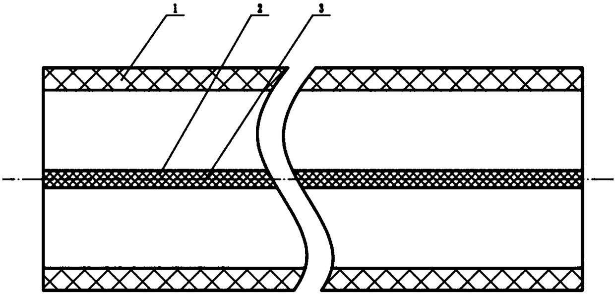
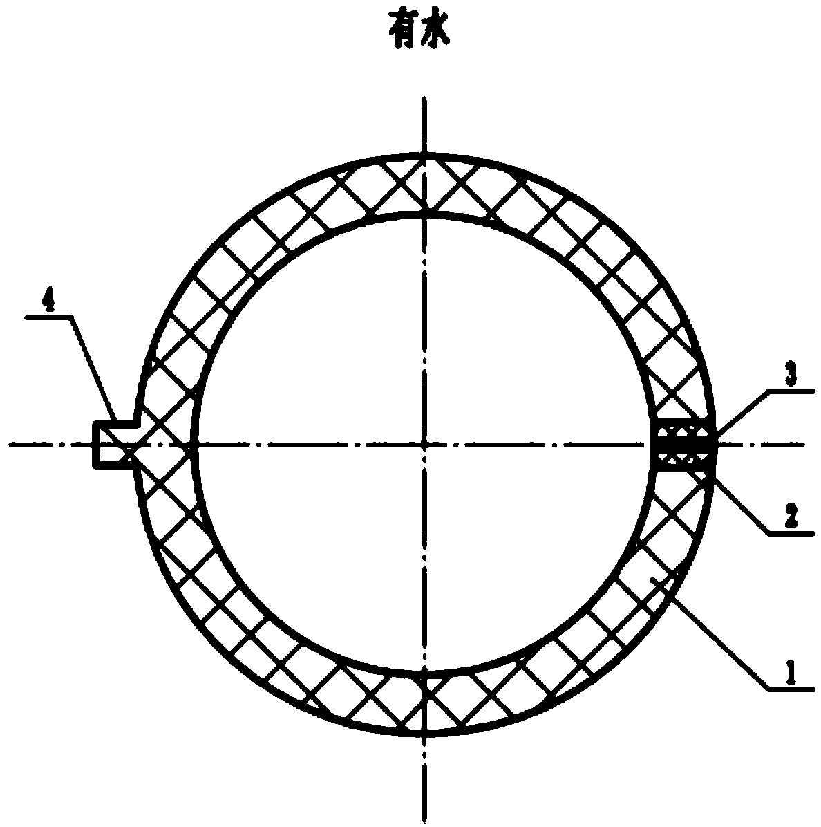
[0025] Such as figure 1 , image 3 As shown, an underground composite seepage pipe of the present invention includes a PP pipe (1), a polymer elastomer groove (2), a seepage hole (3), and a positioning seat (4). It is characterized in that: the PP pipe (1) is compositely connected with the polymer elastomer groove (2), and is extruded at the same time by an extruder; the polymer elastomer groove (2) is provided with water seepage holes (3) , the seepage holes (3) are distributed in the middle of the polymer elastomer groove (2), and the water seepage holes (3) are distributed along the axial direction of the PP pipe (1); the positioning seat (4) is located in the polymer elastomer groove (2) directly below, symmetrically distributed on the outside of the PP pipe (1) with the polymer elastomer groove (2), the polymer elastomer groove (2) is perpendicular to the ground plane and the seepage hole (3) faces the ground upwards, and the positioning seat ( 4) Perpendicular to groun...

example 2

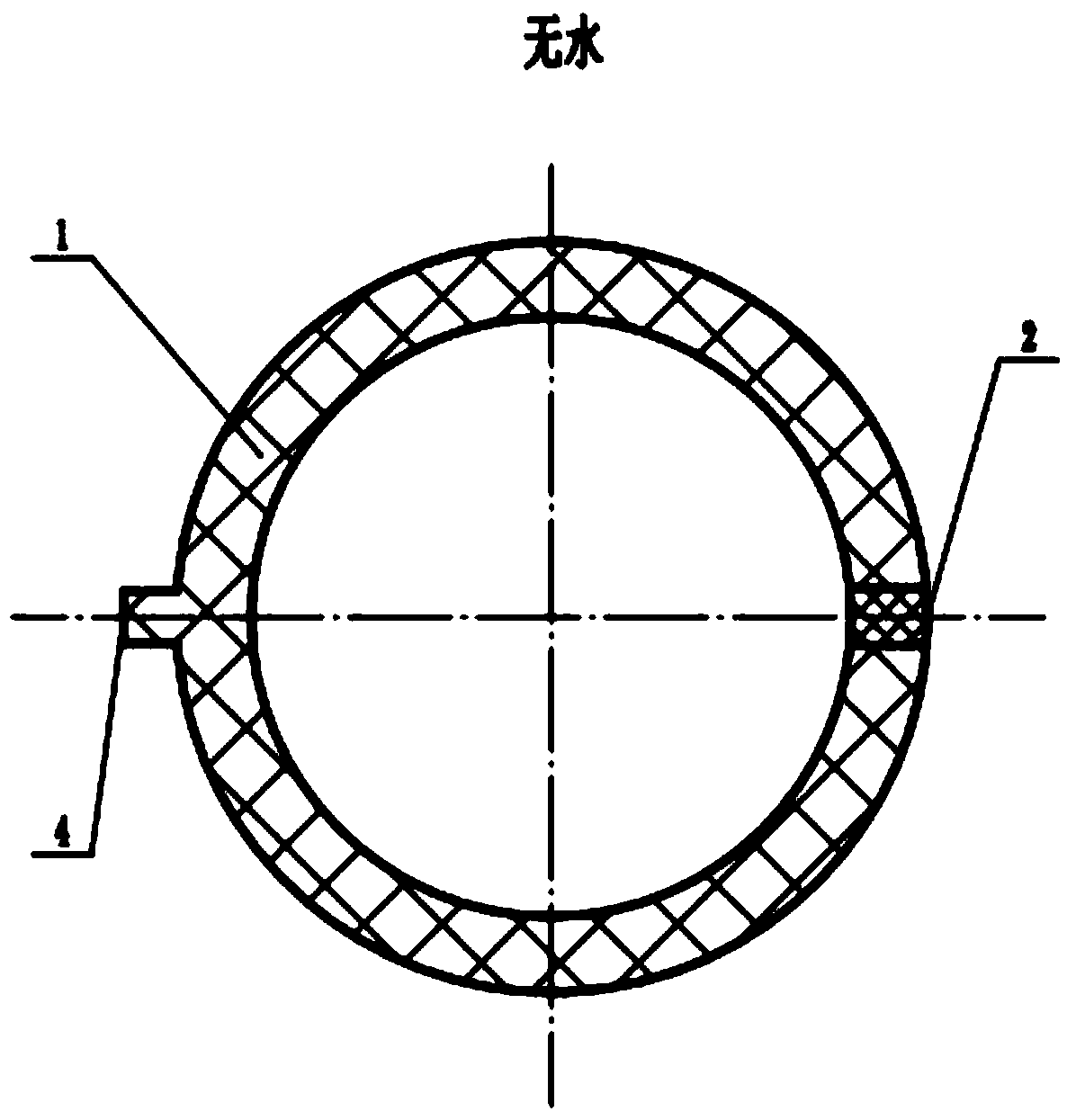
[0027] Such as figure 1 , figure 2 As shown, an underground composite seepage pipe of the present invention includes a PP pipe (1), a polymer elastomer groove (2), a seepage hole (3), and a positioning seat (4). It is characterized in that: the PP pipe (1) is compositely connected with the polymer elastomer groove (2), and is extruded through an extruder at the same time to form; the polymer elastomer groove (2) has a water seepage hole (3) , the seepage holes (3) are distributed in the middle of the polymer elastomer groove (2), and the water seepage holes (3) are distributed along the axial direction of the PP pipe (1); the positioning seat (4) is located in the polymer elastomer groove (2) directly below, symmetrically distributed on the outside of the PP pipe (1) with the polymer elastomer groove (2), the polymer elastomer groove (2) is perpendicular to the ground plane and the seepage hole (3) faces the ground upwards, and the positioning seat ( 4) Perpendicular to gro...


PUM


Abstract

The invention discloses a buried composite seepage pipe. The buried composite seepage pipe comprises polypropylene (PP) pipe, a high-molecular elastomer groove, water seepage holes and positioning seats. The PP pipe is combined and connected with the high-molecular elastomer groove; the high-molecular elastomer groove is provided with the water seepage holes, the water seepage holes are uniformlydistributed in the middle of the high-molecular elastomer groove according to a fixed length, the water seepage holes are distributed along the axial direction of the PP pipe, and the size of the water seepage holes can be automatically adjusted according to the water pressure of a pipeline; and the positioning seats are located right below the high-molecular elastomer groove, are distributed on the outer side of the PP tube and are symmetrically with the high-molecular elastomer groove. The seepage pipe is simple in structure, can automatically adjust the water seepage amount, is high in efficiency, saves water, is stable in positioning and facilitates mechanical and efficient laying.

Description

technical field [0001] The invention relates to water-saving irrigation pipeline technology, in particular to an underground composite seepage pipe. Background technique [0002] As we all know, the traditional irrigation method is ground irrigation, mainly drainage irrigation, sprinkler irrigation and drip irrigation. The defect of these irrigation methods is that the water consumption is far greater than the water required for crop growth, so the waste of water resources is huge, and it is inconvenient for ground cultivation operations. At present, global freshwater resources are scarce, and my country is facing serious overexploitation of groundwater, overexploitation of water resources in the upper reaches of inland rivers, and deterioration of the ecological environment. Water-saving irrigation technologies such as infiltration irrigation are used to maintain sustainable development and utilization of water resources in the future. has great social significance. [000...

Claims


Application Information

Patent Timeline
Patent Type & Authority Applications(China)
IPC IPC(8): A01G25/06
CPCA01G25/06
Inventor 宋纯营
Owner 河北广发农业科技有限公司
Why Eureka
Try Eureka