Pipe bending neutral layer offset position determining method

A technology for determining the method and offset position, which is applied in the field of plastic forming of metal materials, can solve problems such as the difficulty in determining the offset of the neutral layer, and achieve the effect of improving the forming ability

Active Publication Date: 2019-03-01
NORTHWESTERN POLYTECHNICAL UNIV
View PDF6 Cites 8 Cited by
  • Summary
  • Abstract
  • Description
  • Claims
  • Application Information

AI Technical Summary

Problems solved by technology

[0004] The purpose of the present invention is to provide a method for determining the offset position of the neutral layer in pipe bending, which solves the problem of difficulty in determining the offset of the neutral layer in pipe bending in the prior art

Method used


Image

  • Pipe bending neutral layer offset position determining method
  • Pipe bending neutral layer offset position determining method
  • Pipe bending neutral layer offset position determining method

Examples


Embodiment 1

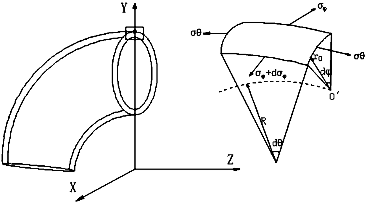
[0066] Such as figure 1 , figure 2 As shown, a method for determining the offset position of the neutral layer in pipe bending includes the following steps:

[0067] Step 1: Static Stress Balance Analysis

[0068] In the section of the bent pipe, X is the geometric central axis, which coincides with the neutral layer before the pipe is bent, Y represents the direction of the bending radius, and the positive direction points to the outer arc of the bend, R is the bending radius, and ρ is the distance between the neutral layer and the bending center. The distance between, y is the distance between the X-axis on the cross-section and any fiber layer, is the calculated angle from any element to the Y axis and any point on the cross section, α is the offset angle of the neutral layer, r 0 is the original radius of the pipe, therefore, the neutral layer offset e can be expressed as

[0069] e=r 0 sinα (1)

[0070] By analyzing a small unit of the bent pipe, the stress state ...

Embodiment 2

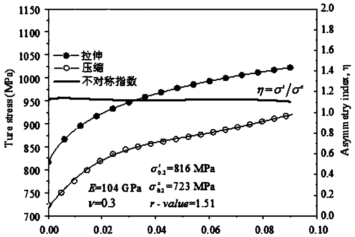
[0115] Such as Figure 3 to Figure 5 As shown, this embodiment 2 is a calculation method for the offset position of the neutral layer in the numerically controlled bending (RDB) of pipes. In Example 2, Ti-3Al-2.5V titanium alloy pipe is selected as the curved pipe, and its specification is Φ12×t0.9mm (pipe outer diameter×wall thickness), which has obvious anisotropy and tension-compression asymmetry . The material properties of the pipes are obtained by uniaxial tensile and compression tests, see image 3 . Introduce an asymmetry index (η) to describe the level of transient tension-compression asymmetric behavior, by η=σ t / σ c Definition, its value is about 1.1. In order to introduce the asymmetric behavior into the mixed neutral layer migration framework, the tensile and compressive stress-strain relationships were fitted by Swift and Shah functions, respectively. The fitting equation is represented by formula (19)

[0116]

[0117] σ is the equivalent stress, an...

Embodiment 3

[0123] Such as Figure 6 , Figure 7As shown, in order to further evaluate the hybrid NLS model, AZ31 pipe and A6063 pipe were used for press bending (PB). The schematic diagram of press bending is shown in Figure 6 As shown, the tooling includes a punch 1, a pipe 2, a support plate 3 and a lower die 4. The specifications of the two pipes are Φ25×t1.5mm. The AZ31 pipe has strong anisotropy, and the A6063 shows a very low tension-compression Asymmetry and thus can be considered a symmetrical material.

[0124] First, the material properties of the pipe are obtained, through the tensile-compression test, the results are as follows Figure 7 , the asymmetry index of the A6063 pipe is about 1.0, which does not change much with the plastic strain; the index of the AZ31 pipe varies greatly, from 0.7 to 1.6, increases in the initial small strain range, and then shows an exponential decay trend. The asymmetric behavior of the AZ31 tube undergoes a complex evolution during plastic ...


PUM


Abstract

The invention discloses a pipe bending neutral layer offset position determining method. The method comprises the following steps of static stress balance analysis, elastic deformation analysis, plastic deformation analysis and analytical-numerical hybrid modeling for solving neutral layer offset. The pipe bending neutral layer offset position determining method is based on an axial force balancemethod, a hybrid analytical-numerical neutral layer frame is built, a neutral layer offset angle alpha is determined, an analytical-numerical hybrid neutral layer offset solving model is built, the model comprehensively considers pipe bending geometrical parameters and complex material performance parameters, the neutral layer offset position can be rapidly and accurately determined, the neutral layer offset rule and mechanism can be rapidly analyzed, and a theoretical basis is laid for innovative development of the pipe bending new technology and improvement of the forming ability.

Description

technical field [0001] The invention relates to the technical field of plastic forming of metal materials, in particular to a method for determining the offset position of the neutral layer of a pipe bending. Background technique [0002] Elbows are known as "artery vessels" and are widely used in aviation, aerospace, shipbuilding, automobiles, energy and chemical industries, and play key roles in medium transmission, heat conduction and structural bearing. In order to meet the application requirements in different fields, the bent pipes come in various sizes and shapes, ranging from micro-nanotubes in diameter to super-large pipes with a diameter of several meters, and the bending shapes include different bending radii, bending angles and spatial orientations. Plastic bending of pipes is an important forming method for pipe bending components. Common pipe bending processes include press bending, roll bending, push bending, numerical control bending, etc. However, no matter...

Claims


Application Information

Patent Timeline
Patent Type & Authority Applications(China)
IPC IPC(8): B21D7/00
CPCB21D7/00
Inventor 李恒马俊贺子芮杨恒黄卫良刘浩然
Owner NORTHWESTERN POLYTECHNICAL UNIV
Why Eureka
Try Eureka