Pipeline automatic cleaning and grinding device
An automatic cleaning and pipeline technology, used in grinding drives, grinding machines, grinding racks, etc., can solve the problems of inability to adjust the pipeline, blockage of the pipeline, poor cleaning effect, etc., to achieve strong applicability, improved efficiency, and cleaning efficiency. high effect
- Summary
- Abstract
- Description
- Claims
- Application Information
AI Technical Summary
Problems solved by technology
Method used
Image

Examples
specific Embodiment approach 1
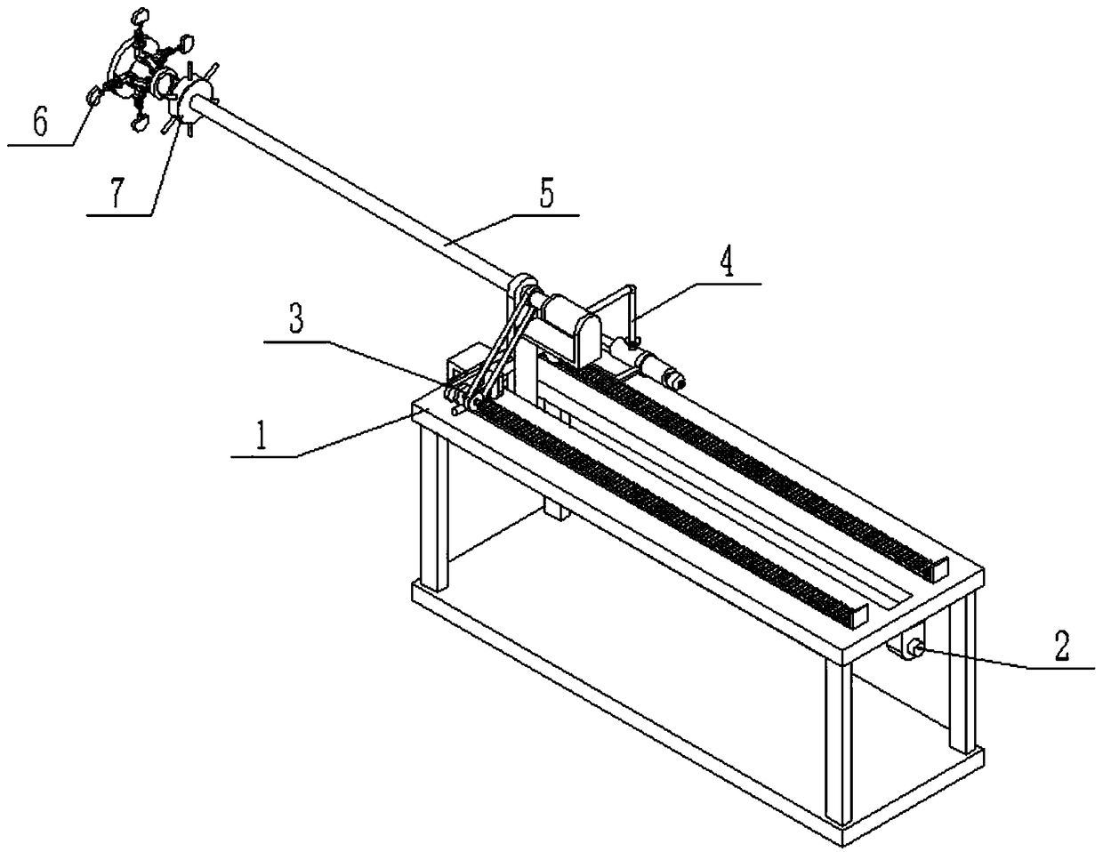
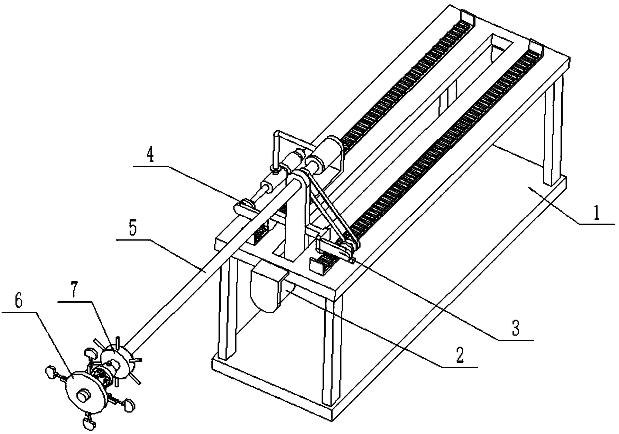
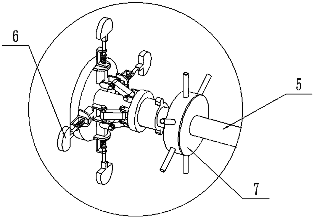
[0030] Such as Figure 1-11As shown, an automatic pipeline cleaning and polishing device includes a frame assembly 1, a displacement control mechanism 2, a grinding linkage wheel 3, a cleaning linkage wheel 4, a rotating tube 5, a polisher 6 and a cleaner 7, and is characterized in that: The frame assembly 1 includes an upper shelf plate 1-1, a lower shelf plate 1-2, a support leg 1-3, a rectangular sliding hole 1-4, a front linkage rack 1-5 and a rear linkage rack 1-6; The four corners of the bottom surface of the plate 1-1 are respectively fixedly connected to the four corners of the top surface of the lower shelf plate 1-2 by a supporting leg 1-3; the middle end of the upper shelf plate 1-1 is provided with a rectangular sliding hole 1-4; The front and rear ends of the top surface of the upper shelf plate 1-1 are respectively fixedly connected to the front linkage rack 1-5 and the rear linkage rack 1-6, and the rectangular sliding holes 1-4 are located at the front linkage ...
specific Embodiment approach 2
[0033] Such as Figure 1-11 As shown, the rotating pipe 5 includes a cylindrical pipe 5-1, a driven sprocket 5-2, a water inlet cylinder 5-3 and a cylinder seat plate 5-4; a cylindrical pipe 5-1, a driven sprocket 5-2 and a water inlet cylinder The axes of 5-3 are collinear and provided with axial positioning; the right end of the cylindrical tube 5-1 is sealed and rotatably connected to the left side of the water inlet cylinder 5-3, and the connection between the cylindrical tube 5-1 and the water inlet cylinder 5-3 There is a dynamic seal between them, and the cylindrical tube 5-1 is connected to the water inlet cylinder 5-3; the water inlet cylinder 5-3 is fixedly connected to the horizontal slide plate 2-5 through the cylinder seat plate 5-4; the water inlet cylinder 5-3 is A water inlet hole is provided; the right end of the cylindrical tube 5-1 is fixedly connected to the driven sprocket 5-2; the cylindrical tube 5-1 is connected to the upper end of the horizontal slide ...
specific Embodiment approach 3
[0034] Such as Figure 1-11 As shown, the grinding linkage wheel 3 includes a first gear 3-1, a first wheel shaft 3-2, a first worm 3-3, a first worm wheel 3-4, a first linkage shaft 3-5, and a drive sprocket 3 -6. The first shaft frame plate 3-7 and the first fixed plate 3-8; the axes of the first gear 3-1, the first wheel shaft 3-2 and the first worm 3-3 are collinear and provided with axial positioning The axes of the first worm gear 3-4, the first linkage shaft 3-5 and the driving sprocket 3-6 are collinear and provided with axial positioning; the first gear 3-1 is fixedly connected to the first wheel shaft 3-2 On the top, the front linkage rack 1-5 is meshed and connected to the first gear 3-1; one end of the first wheel shaft 3-2 is connected to the first fixed plate 3-8 through the rotation fit of the bearing with seat, and the first wheel shaft 3 The other end of -2 is fixedly connected to the first worm 3-3, the first worm 3-3 is meshed and connected to the first wor...
PUM
 Abstract
Description
Claims
Application Information