Optical assembly with backlight monitoring

An optical component and backlight technology, which is applied in the field of optical communication, can solve the problems of complex production process, high cost, and difficult control of the splitting ratio of the beam splitting film, so as to improve the quality of high-speed signal transmission, reduce the cost, and eliminate the influence of stray light. Effect

Pending Publication Date: 2019-03-01
ZHOUKOU NORMAL UNIV
View PDF1 Cites 4 Cited by
  • Summary
  • Abstract
  • Description
  • Claims
  • Application Information

AI Technical Summary

Problems solved by technology

[0003] Chinese patent 201410759532.3 proposes an optical component with backlight monitoring for high-speed transmission. The optical component uses a splitter diaphragm to split the incident light. Part of the light is transmitted to the optical fiber, and the other part is used as a backlight monitor. The splitter diaphragm The production process is complicated, the cost is high, and the splitting ratio is difficult to control

Method used


Image

  • Optical assembly with backlight monitoring
  • Optical assembly with backlight monitoring
  • Optical assembly with backlight monitoring

Examples


Embodiment Construction

[0025] In order to make the purpose, technical solutions and advantages of the present invention clearer, the technical solutions in the embodiments of the present invention will be clearly described below in conjunction with the accompanying drawings in the embodiments of the present invention. Obviously, the described embodiments are part of the present invention Examples, not all examples. Based on the embodiments of the present invention, all other embodiments obtained by persons of ordinary skill in the art without making creative efforts belong to the protection scope of the present invention.

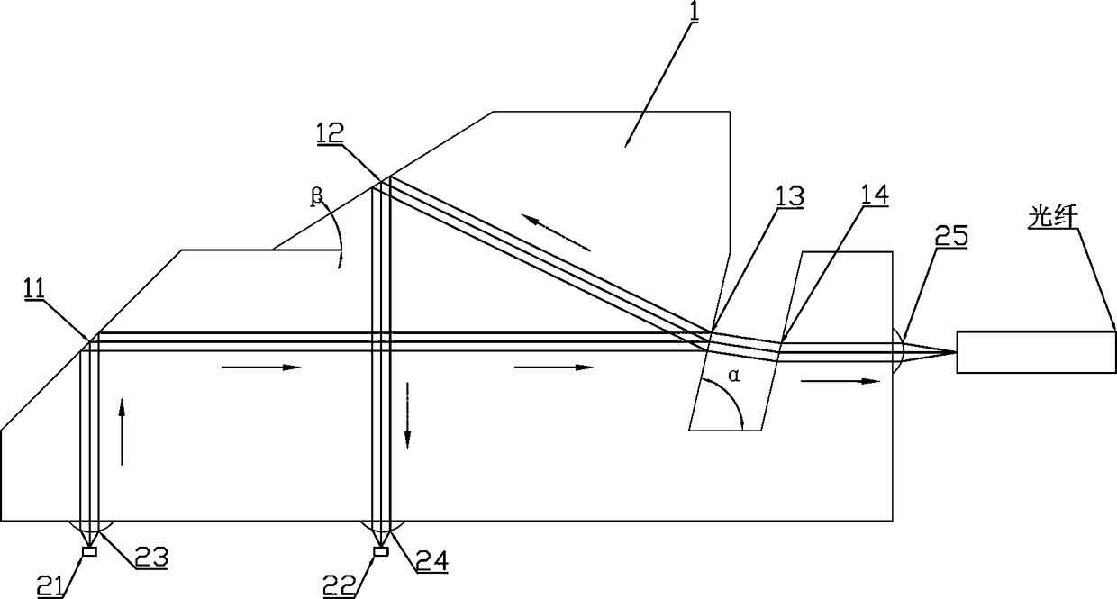
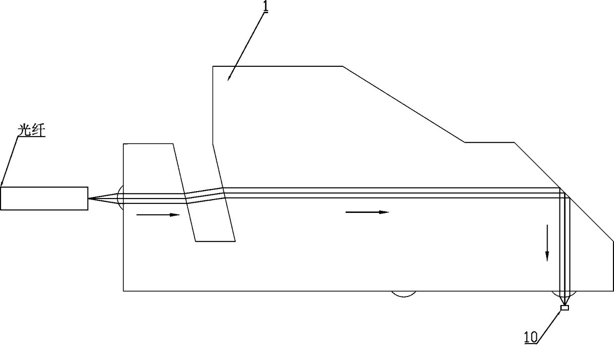
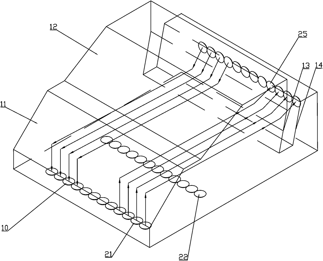
[0026] Figure 1 to Figure 3 A schematic structural diagram of an optical component with backlight monitoring provided by an embodiment of the present invention. to combine Figure 1 to Figure 3 , the optical component mainly includes: a transmissive base 1 and at least one group of optical transmission units;

[0027] The transmissive substrate 1 is provided with a first inte...


PUM


Abstract

The invention provides an optical assembly with backlight monitoring. The assembly comprises a transmission substrate and at least one set of optical transmission units. A first interface, a second interface, a third interface, and a fourth interface are arranged on the transmission substrate; the first interface and the second interface are total-reflection interfaces; the third interface and thefourth interface serve as parallel interfaces for each other; and an air gap is formed between the third interface and the fourth interface. The optical transmission units include VCSEL chips, MPD chips, incident collimating lenses, first focusing lenses and second focusing lenses. The first interface, the third interface and the fourth interface cooperate with each other to form a first opticalpath; the second interface and the third interface cooperate with each other to form a second optical path; and the first optical path and the second optical path are used for front light transmissionand backlight monitoring. Therefore, problems of many materials and complicated optical path of the conventional optical assembly with the backlight monitoring scheme are solved.

Description

technical field [0001] The invention relates to the technical field of optical communication, in particular to an optical component with backlight monitoring. Background technique [0002] With the rapid growth of Internet, cloud computing, and big data services, the large-scale construction of large-capacity and high-bandwidth data centers is being promoted, and the requirements for data transmission efficiency are getting higher and higher. In the field of optical communication, vertical cavity surface emitting laser (Vertical Cavity Surface Emitting Laser; VCSEL) is used as the light source to achieve high bandwidth transmission. In practical applications, the VCSEL laser is in a non-airtight environment, and its performance is easily affected by the environment, especially the output optical power. In order to ensure the stability of the light source during use, the output optical power needs to be monitored. [0003] Chinese patent 201410759532.3 proposes an optical co...

Claims


Application Information

Patent Timeline
Patent Type & Authority Applications(China)
IPC IPC(8): G02B6/42H01S5/06H01S5/183
CPCG02B6/4286G02B6/4204G02B6/4214G02B6/4296H01S5/06H01S5/183
Inventor 丁新慧刘夏吟吴聪张文娟周文刚秦杰
Owner ZHOUKOU NORMAL UNIV
Why Eureka
Try Eureka