
Simulation method of opening position of energy release hole of explosion-proof device for high-voltage cable connector

An explosion-proof device, high-voltage cable technology, applied in design optimization/simulation, electrical digital data processing, special data processing applications, etc., can solve problems such as unfavorable waterproofing, optimization, complicated design, etc. The effect of improving the protection accuracy

Active Publication Date: 2019-03-01
GUANGDONG POWER GRID CO LTD +1
View PDF1 Cites 8 Cited by
  • Summary
  • Abstract
  • Description
  • Claims
  • Application Information

AI Technical Summary

Problems solved by technology

In practical applications, it is more cumbersome to design multiple energy dissipation holes at the same time, and it is not conducive to waterproofing, and it is difficult to achieve the expected protection effect
In the past, the research on the opening position and the opening position of the scheme of using two larger openings for the energy dissipation hole basically relied on the experience of the manufacturer, and there was a large deviation in practical application, and the optimization of the protection effect could not be achieved.

Method used


Image

  • Simulation method of opening position of energy release hole of explosion-proof device for high-voltage cable connector
  • Simulation method of opening position of energy release hole of explosion-proof device for high-voltage cable connector
  • Simulation method of opening position of energy release hole of explosion-proof device for high-voltage cable connector

Examples


Embodiment 1

[0043] Such as Figure 2 to Figure 8 Shown is the embodiment of the simulation method of the opening position of the energy release hole of the high-voltage cable joint explosion-proof device of the present invention, comprising the following steps:

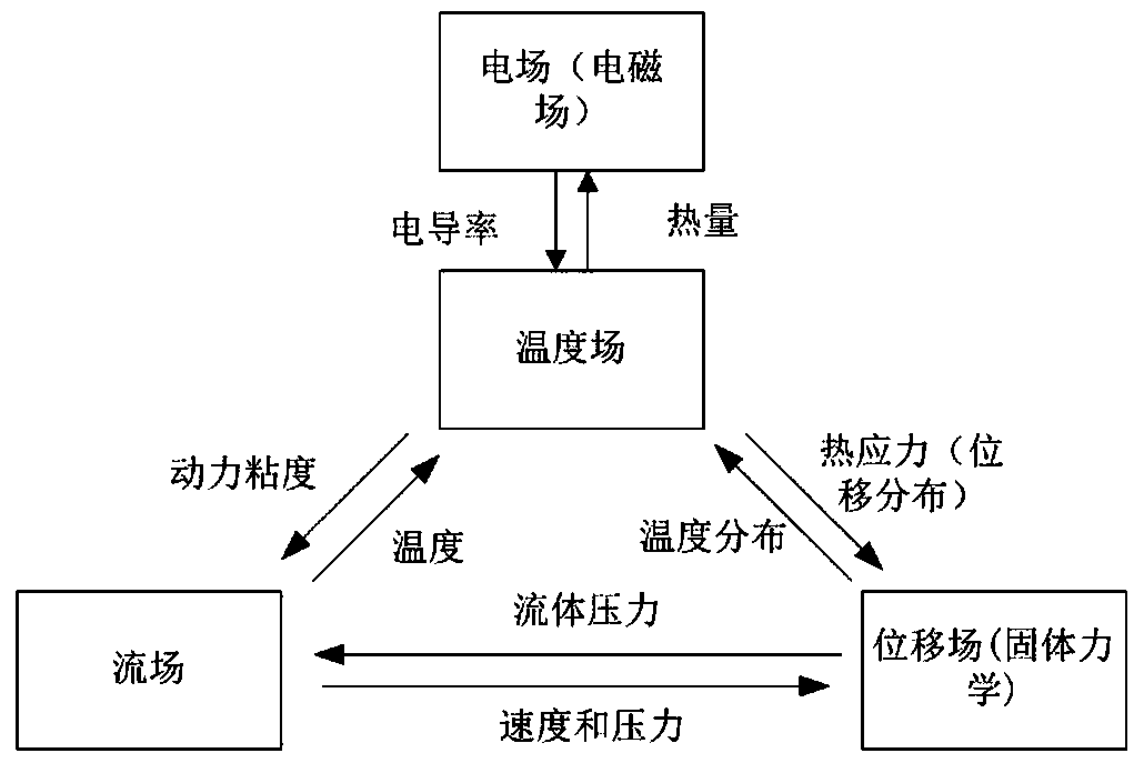
[0044]S1. According to the geometric parameters of each part of the accessories produced by the accessory manufacturer and the electric field strength of the material, establish a thermal-fluid-solid physical model of the high-voltage cable joint explosion-proof device;

[0045] S2. Coupling the thermal-fluid-solid physical model of the high-voltage cable joint explosion-proof device described in step S1 with multi-physics, and solving it by a multi-layer iterative algorithm;

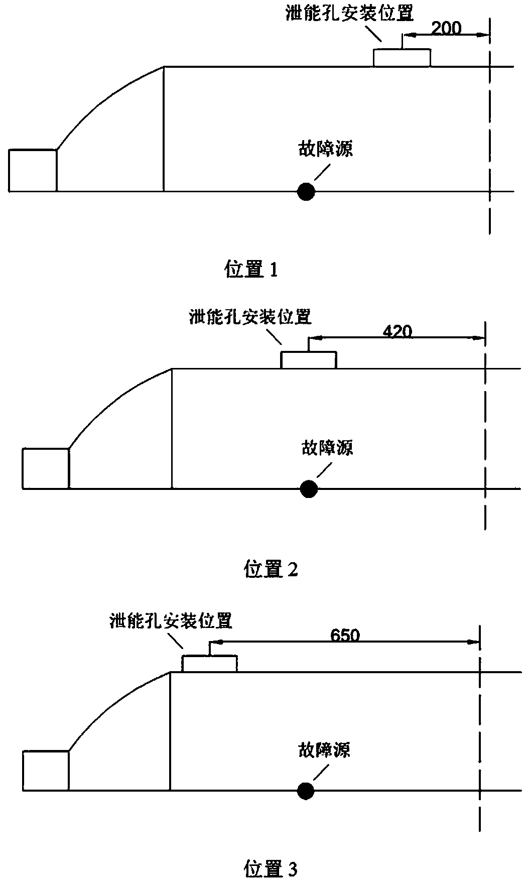
[0046] S3. By simulating the internal airflow velocity and pressure distribution of the explosion-proof device at different time points, calculate the pressure release rate at the opening of the energy release hole at different installation positions;

[...


PUM


Abstract

The invention relates to the technical field of explosion-proof devices for high-voltage cable joints, More specifically, the invention relates to a simulation method for the position of the vent holeopening of a high-voltage cable joint explosion-proof device, which comprises the following steps of: adopting COMSOL Multiphysics multi-physical field coupling simulation software to construct models of different types of vent hole explosion-proof devices; adopting the coupling mode of heat-Flow-solid multi-physical field is used to calculate the pressure release velocity change trend at different instantaneous corresponding to the energy relief holes at different installation positions. Based on the analysis of the changing trend of the pressure release velocity at different time corresponding to the energy release holes in different mounting positions, the optimal mounting position of the energy release holes is designed, which can improve the design accuracy and reduce the test workload by comprehensively considering the position where the specific type of cable connector is most prone to failure. The invention can optimize the installation position design of the energy dissipation hole of the explosion-proof device of the high-voltage cable joint, saves the test cost, improves the protection precision, and provides a reliable theoretical calculation method for the explosion-proof device design.

Description

technical field [0001] The invention relates to the technical field of simulation of explosion-proof devices for high-voltage cable joints, and more particularly, to a simulation method for opening positions of energy-discharging holes of explosion-proof devices for high-voltage cable joints. Background technique [0002] In order to prevent the insulation breakdown of the intermediate joint of the power cable, causing the explosion accident of the intermediate joint of the power cable, and causing the line to trip and cut off the power, an explosion-proof device for the intermediate joint of the power cable must be adopted. There are regulations in the industry that clearly point out that the outermost layer of non-directly buried cable joints should be covered with flame-retardant materials, and oil-filled cable joints and joints of densely laid medium-voltage cables should be sealed with fire-resistant and explosion-proof boxes. The explosion-proof device of the intermedi...

Claims


Application Information

Patent Timeline
IPC IPC(8): G06F17/50
CPCG06F30/17G06F2113/16G06F2119/06G06F30/23Y02E60/00
Inventor 黄顺涛仇炜杨鑫孙廷玺崔江静裴星宇周锋方义治梁振
Owner GUANGDONG POWER GRID CO LTD
Learn More