
Method and device for controlling delay jitter at receiving end

A control method and technology of a control device, applied in the field of communication, can solve the problems of reducing the usage scenarios of 100G/400G DSP chips, the influence of delay jitter on optical communication quality cannot be ignored, system reliability and performance impact, etc., so as to reduce the delay Jitter, reduce impact, ensure the effect of stability

Active Publication Date: 2020-06-05
SANECHIPS TECH CO LTD
View PDF3 Cites 0 Cited by
  • Summary
  • Abstract
  • Description
  • Claims
  • Application Information

AI Technical Summary

Problems solved by technology

[0003] However, with the improvement of transmission rate and the expansion of transmission distance, the impact of delay jitter on optical communication quality cannot be ignored.
In the Optical Transport Network (OTN) system, the delay jitter in the transmission link and the reception link will cause data signal transmission damage, which will have a negative impact on the reliability and performance of the entire system
Currently, mainstream digital signal processing (DSP) chips in the industry have no special processing for this. In 100G / 400G long-distance transmission services, 100G / 400G pass-through services and 100G / 400G loopback services, system reliability and Performance will be affected; for services with special requirements on delay requirements, such as 100GE (Gigabit Ethernet) / 400GE services, it cannot meet the requirements, thus greatly reducing the usage scenarios of 100G / 400G DSP chips

Method used


Image

  • Method and device for controlling delay jitter at receiving end
  • Method and device for controlling delay jitter at receiving end
  • Method and device for controlling delay jitter at receiving end

Examples


Embodiment Construction

[0036] In order to make the purpose, technical solution and advantages of the present invention more clear, the embodiments of the present invention will be described in detail below in conjunction with the accompanying drawings. It should be noted that, in the case of no conflict, the embodiments in the present application and the features in the embodiments can be combined arbitrarily with each other.

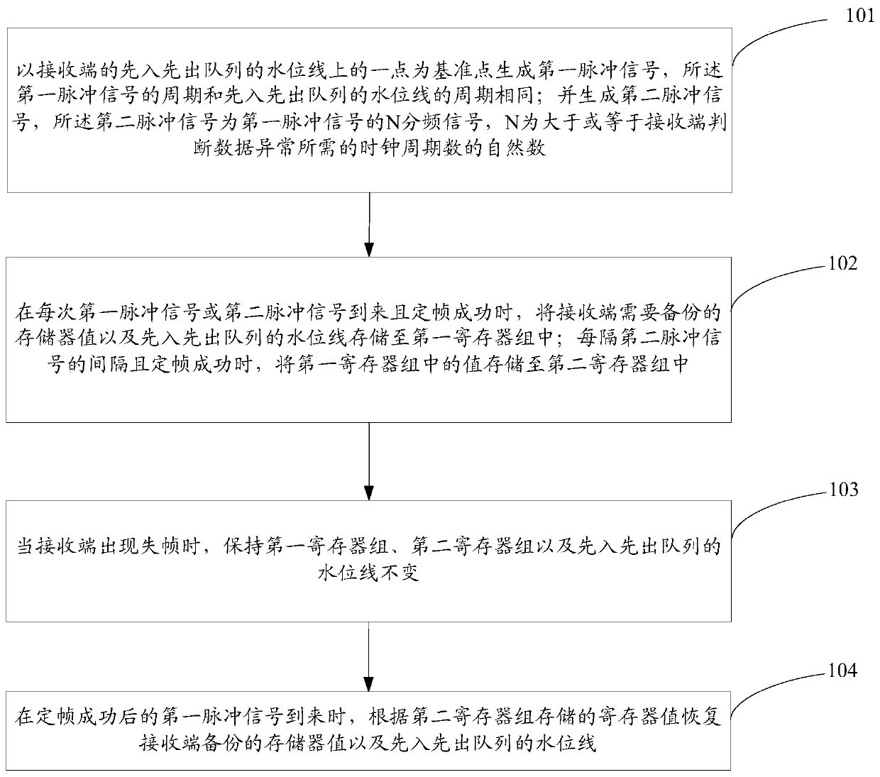
[0037] like figure 1 As shown, a method for controlling delay jitter at a receiving end according to the present invention includes the following steps:

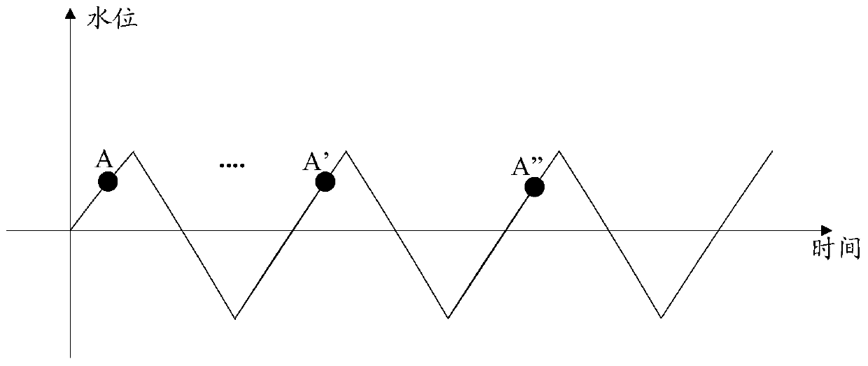
[0038] Step 101: Taking a point on the water level of the first-in-first-out queue at the receiving end as a reference point to generate a first pulse signal, the period of the first pulse signal is the same as the period of the water level of the first-in-first-out queue; generate a second pulse signal , the second pulse signal is an N frequency-divided signal of the first pulse signal, and N is a natural number greater t...


PUM


Abstract

The invention discloses a control method and device for the delay jitter of a receiving end. The control method comprises the steps of: generating a first pulse signal by using one point on a gaugingline of an FIFO (First Input First Output) queue of the receiving end as a datum point; generating an N frequency-divided signal of the first pulse signal, i.e., a second pulse signal; every time thefirst pulse signal arrives and is succeeded in frame synchronization, storing a storage value and the gauging line of the FIFO queue, which need to be backed up, into a first register set; at each interval of the second pulse signal, when frame synchronization is successful, storing values in the first register set into a second register set; when frame dropping occurs, keeping the first registerset, the second register set and the gauging line of the FIFO queue unchanged; and when the first pulse signal succeeded in frame synchronization arrives, recovering the storage value and the gaugingline of the FIFO queue, which are backed up. According to the invention, by using two register sets for backing up and storing the storage value and the gauging line of the FIFO queue, the stability of data traffic of the receiving end is ensured, and the delay jitter is reduced.

Description

technical field [0001] The invention relates to the field of communication technology, in particular to a method and device for controlling delay jitter at a receiving end. Background technique [0002] The rapid growth of data services in recent years has put forward higher requirements for transport networks: large capacity, low cost, fast and flexible service scheduling, strong scalability and high reliability. At present, the development of optical fiber transmission network has gone through the following stages: space division multiplexing (Space Division Multiplexing, SDM) stage, time division multiplexing (Time Division Multiplex, TDM) stage and wavelength division multiplexing (Wavelength Division Multiplexing, WDM) stage , the currently used optical fiber transmission system is mainly based on the wavelength division multiplexing system. With the continuous development of communication technology, the current commercial 40G (Gigabit) wavelength division transmissio...

Claims


Application Information

Patent Timeline
Patent Type & Authority Patents(China)
IPC IPC(8): H04J3/06H04J3/14H04J14/02
CPCH04J3/0635H04J3/0682H04J3/14H04J14/02
Inventor 付华杰
Owner SANECHIPS TECH CO LTD
Learn More