A laser scanning packaging system and method
A laser scanning and packaging system technology, applied in manufacturing tools, glass manufacturing equipment, glass remolding, etc., can solve the problems of uneven energy distribution and poor applicability in the packaging area, and improve the uniformity of energy distribution and process applicability. The effect of improving air tightness
- Summary
- Abstract
- Description
- Claims
- Application Information
AI Technical Summary
Problems solved by technology
Method used
Image
Examples
Embodiment 1
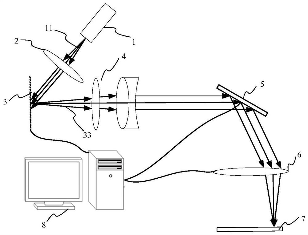
[0096] In Embodiment 1, the glass encapsulation method is used to encapsulate an annular encapsulation area, the modulated light spot moves at a uniform speed along the extension direction of the encapsulation area for scanning, and the glass frit is sintered for encapsulation.
[0097] The shape of the modulated light spot can be adjusted to a circular light spot or a fan-shaped light spot as required.
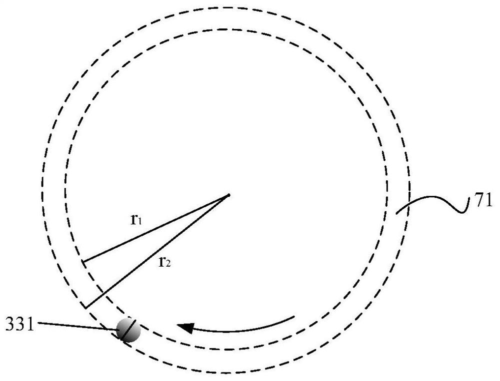
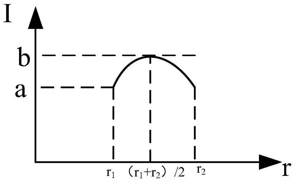
[0098] see figure 2 and image 3 , when the spot shape is a circular spot 331, the energy in the circular spot 331 is given by r 1 to r 2 Gradually increasing, when the circular spot 331 scans at a constant speed along the extending direction of the annular packaging area 71, it is required that in the annular packaging area 71, the energy in the annular packaging area 71 is evenly distributed, that is, in the radial direction in the annular packaging area 71, by r 1 to r 2 The energy of the annular encapsulation area 71 in the area is evenly distributed, therefore, the...
Embodiment 2
[0103] see Image 6 , in this embodiment, the laser scanning glass packaging method is used to package a rectangular packaging area 72, the rectangular packaging area includes several linear packaging areas and several round corner packaging areas, the linear packaging area and the described Round corner package areas are connected alternately, see Image 6 and Figure 7 , in the rectangular packaging area 72, taking one of the round corner packaging areas as an example, the two linear packaging areas connected to the two ends of the round corner packaging area 723 are defined as the first linear packaging area 721 and the second linear packaging area 721. Packaging area 722, the first linear packaging area 721 includes a first packaging area 721a and a second packaging area 721b, and the second linear packaging area 722 includes a third packaging area 722a and a fourth packaging area 722b, The first encapsulation area 721a, the second encapsulation area 721b, the round corn...
Embodiment 3
[0123] This embodiment is used to package a rectangular package area, and the shape of the modulated light spot is a circular light spot 331 and / or a rectangular light spot 332. In the first package area 721a, the second package area 721b, the circle In the corner encapsulation area 723 , the third encapsulation area 722 a and the fourth encapsulation area 722 b , when the modulated light spot moves to the boundary of two adjacent areas, the shape of the modulated light spot is transformed.
[0124] see Figure 13 , Figure 13 The first packaging method provided for the third embodiment, the modulated light spot in the first packaging area 721a, the round corner packaging area 723 and the fourth packaging area 722b is a circular light spot 331, and in the second packaging area 721b and the modulation spot in the third encapsulation region 722a is a rectangular spot 332; please refer to Figure 14 , Figure 14 The second packaging method provided for the third embodiment, the ...
PUM
| Property | Measurement | Unit |
|---|---|---|
| size | aaaaa | aaaaa |
Abstract
Description
Claims
Application Information
 - R&D
- Intellectual Property
- Life Sciences
- Materials
- Tech Scout
- Unparalleled Data Quality
- Higher Quality Content
- 60% Fewer Hallucinations
Browse by: Latest US Patents, China's latest patents, Technical Efficacy Thesaurus, Application Domain, Technology Topic, Popular Technical Reports.
© 2025 PatSnap. All rights reserved.Legal|Privacy policy|Modern Slavery Act Transparency Statement|Sitemap|About US| Contact US: help@patsnap.com


