Internal structure of furnace body

A technology of internal structure and furnace body, which is applied to parts, furnaces, and furnace cooling of pumping devices for elastic fluids. It can solve the problems of heavy weight of glass fiber felt, reduced service life of the shell, and difficult installation of the inner tank. Achieve the effect of improving connection strength and stability, ensuring stability and reliability, and good thermal insulation effect

A technology of internal structure and furnace body, which is applied to parts, furnaces, and furnace cooling of pumping devices for elastic fluids. It can solve the problems of heavy weight of glass fiber felt, reduced service life of the shell, and difficult installation of the inner tank. Achieve the effect of improving connection strength and stability, ensuring stability and reliability, and good thermal insulation effect

CN109425221AInactive Publication Date: 2019-03-05张跃

Image

  • Internal structure of furnace body
  • Internal structure of furnace body
  • Internal structure of furnace body

Examples


Embodiment Construction

[0047] The present invention will be further described in detail below in conjunction with the accompanying drawings and specific embodiments.

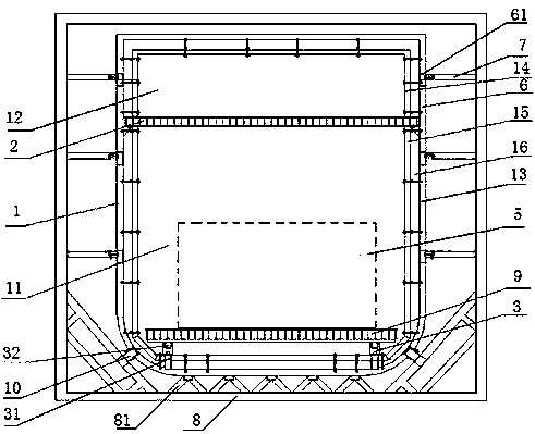
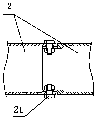
[0048] Such as figure 1 Shown: an internal structure of a furnace body, including an inner tank 1, the cavity of the inner tank 1 is connected with a partition 2, and the partition 2 divides the inner tank into at least two cavities, one of which is a working cavity 11; An inner roller mechanism 3 is arranged in the working chamber 11, and a workpiece 5 is placed on the inner roller mechanism 3; a high-temperature fan is arranged on one side of the inner tank 1.

[0049] The above scheme has the following advantages: (1) By setting the partition plate 2, the working chamber is separated from other chambers, such as the heating chamber, which can avoid the high temperature of the part of the workpiece near the heating body, while the temperature of other parts is low, resulting in The workpiece is heated unevenly; (2) By setting the i...


PUM

PropertyMeasurementUnit
shear strengthaaaaaaaaaa

Abstract

The invention provides an internal structure of a furnace body. The internal structure comprises a liner; chamber bodies of the liner are connected with a partition plate; the partition plate is usedfor dividing the liner into at least two chamber bodies; one chamber body is a working chamber; an internal rolling wheel mechanism is arranged inside the working chamber; a workpiece is placed on theinternal rolling wheel mechanism; and a fan is arranged at one side of the liner. On one hand, the internal structure provided by the invention can realize uniform heating or cooling of the workpiece; and on the other hand, the inside of the liner is made from a high temperature resisting material and can resist a temperature larger than or equal to 450 DEG C, so the internal structure is especially applicable to places which can bear strong burning and high pressure.

Description

technical field [0001] The invention relates to a furnace body structure, in particular to an inner structure of a furnace body. Background technique [0002] The existing body of furnace mainly has the following defects: [0003] First, the working chamber and the heating chamber are mostly located in different chambers, resulting in a complex structure; or the heating chamber and the working chamber are in the same chamber, but there is no isolation between the two. If the workpiece is close to the heating body, the workpiece The temperature at the end close to the heating body will be higher than the temperature at other positions, resulting in uneven heating of the workpiece. Even if there is a partition in the furnace body, on the one hand, it is not suitable for high-temperature environments, and its strength is low, so it cannot be used in high-burning and pressure-bearing occasions, and the versatility is poor; on the other hand, the existing partitions have fixed d...

Claims


Application Information

Patent Timeline
05 Mar 2019
Publication
CN109425221A
IPC
F27B9/02; F27B9/30; F27B9/34
CPC
B23K1/008; B23K3/00; B23K3/04; B23K3/053; B23K3/085; F04D25/06; F04D29/5806; F04D29/582
Inventors
张跃