Supercharge Your Innovation With Domain-Expert AI Agents!

Image quality compensation device and method

The technology of a compensation device and compensation method, which is applied in the field of lithography, can solve the problems of unsatisfactory compensation aberration, limitation of compensation items, poor compensation ability of asymmetric images, etc.

Active Publication Date: 2019-03-05
SHANGHAI MICRO ELECTRONICS EQUIP (GRP) CO LTD
View PDF3 Cites 1 Cited by
  • Summary
  • Abstract
  • Description
  • Claims
  • Application Information

AI Technical Summary

Problems solved by technology

[0010] The present invention provides an image quality compensation device and method to solve the problems in the prior art that the compensation ability for asymmetric aberrations is poor, the compensable items are relatively limited, and all aberrations cannot be compensated

Method used


Image

  • Image quality compensation device and method
  • Image quality compensation device and method
  • Image quality compensation device and method

Examples


Embodiment Construction

[0040] The present invention is described in detail below in conjunction with accompanying drawing:

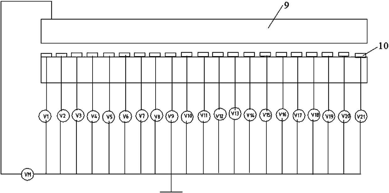
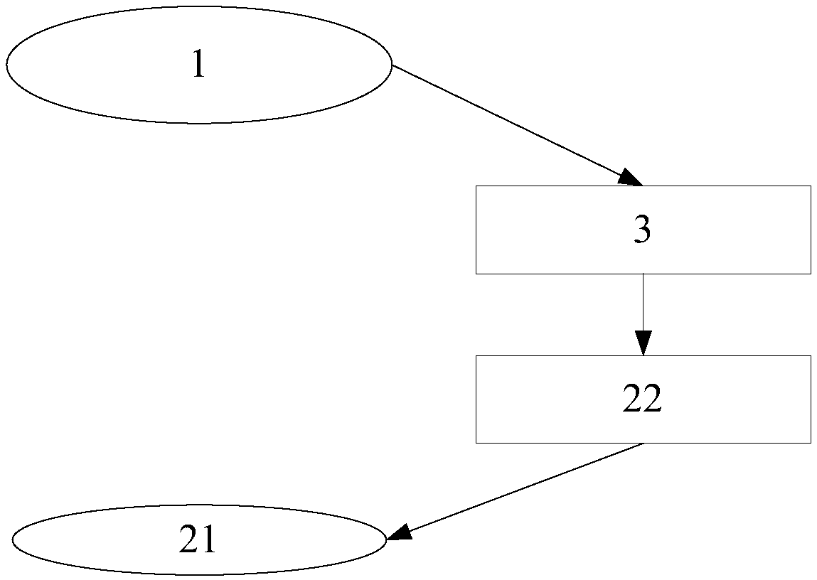
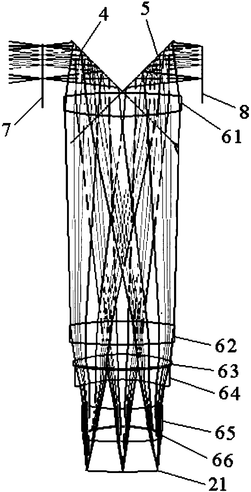
[0041] Such as figure 2 As shown, the present invention provides an image quality compensation device, comprising an objective lens unit 1, an image quality compensation unit 2 and an image quality detection unit 3 for detecting the image quality of the objective lens unit 1, and the image quality compensation unit 2 includes The thin film reflection module 21 arranged in the optical path of the objective lens unit 1 and the array deformation control module 22 respectively connected to the image quality detection unit 3 and the thin film reflection module 21 . Specifically, the image quality data of the objective lens unit 1 detected by the image quality detection unit 3 can be represented by Zernike (Zernick) polynomials, so the process of detection is to measure the Zernike coefficients 1 to 37 items corresponding to multiple points on the image plane numerical value, ther...


PUM


Abstract

The invention discloses an image quality compensation device and method. The device comprises an objective lens unit, an image quality compensation unit and an image quality detection unit used for detecting the image quality of the objective lens unit, wherein the image quality compensation unit comprises a film reflection module arranged in the light path of the objective lens unit, and a deformation control module independently connected with the image quality detection unit and the film reflection module. According to the image quality data, which is detected by the image quality detectionunit, of the objective lens unit, the regulation amounts of different positions on the film reflection module can be obtained, and the deformation control module carries out vertical direction regulation according to the regulation amounts of different positions on the film reflection module to obtain a required face type. By use of the device, the constant terms, which are distributed along a field of view, of all large-range aberrations can be accurately compensated, and in addition, the problems of low regulation accuracy, inaccurate regulation amounts and the like since large external force is required for generating the required face type for a lens with large thickness when image quality compensation is carried out in a traditional active deformation mechanism are completely avoided.

Description

technical field [0001] The invention relates to the field of photolithography technology, and in particular to an image quality compensation device and method. Background technique [0002] In semiconductor packaging technology, lithography objective lenses used to manufacture integrated circuit chips usually have high resolution and large depth of focus to achieve the preparation of highly integrated chips. At the same time, it is also required that the optical imaging system used for projection exposure has a good image quality compensation capability to meet the image quality requirements of the exposure area during chip preparation. With the continuous improvement of lithographic imaging technology, while the feature size of the chip is continuously shrinking, the requirements for aberrations generated in the optical system are more stringent. Therefore, improving the image quality of the optical imaging system is a key factor for preparing chips with good overall perfo...

Claims


Application Information

Patent Timeline
Patent Type & Authority Applications(China)
IPC IPC(8): G03F7/20
CPCG03F7/70433G03F7/70483G03F7/706G02B26/08G03F7/20
Inventor 韩建郭银章
Owner SHANGHAI MICRO ELECTRONICS EQUIP (GRP) CO LTD
Features
  • R&D
  • Intellectual Property
  • Life Sciences
  • Materials
  • Tech Scout
  • Unparalleled Data Quality
  • Higher Quality Content
  • 60% Fewer Hallucinations
Learn More