
Combined magnetic media, magnetic medium pile, intermittent magnetic separation device, vertical ring high-gradient magnetic separator and methods for magnetic concentration

A high-gradient magnetic separator and magnetic medium technology, which is applied in the fields of magnetic separators and magnetic ore separators, magnetic medium stacks, and magnetic media, can solve the problems of the decline in the recovery rate of magnetic minerals, the difficulty in adjusting the feeding flow rate, and the inability to apply them. Improved recovery, elimination of mechanical inclusions, and easy handling

Pending Publication Date: 2019-03-08
CENT SOUTH UNIV
View PDF0 Cites 0 Cited by
  • Summary
  • Abstract
  • Description
  • Claims
  • Application Information

AI Technical Summary

Problems solved by technology

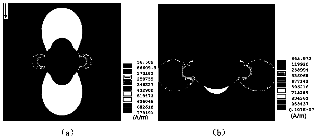
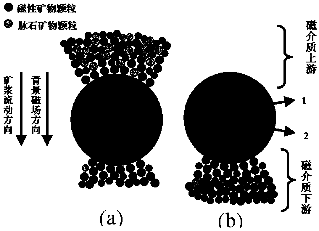
Increasing the feeding speed can eliminate the accumulation of magnetic particles in the upstream of the medium (the side of the medium facing the pulp flow), and the magnetic particles are captured in the downstream of the medium (the side facing away from the pulp flow), which can avoid mechanical inclusions, but will cause magnetic minerals The sharp drop in the recovery rate and the difficult adjustment of the feed flow rate in production, so it cannot be applied

Method used


Image

  • Combined magnetic media, magnetic medium pile, intermittent magnetic separation device, vertical ring high-gradient magnetic separator and methods for magnetic concentration
  • Combined magnetic media, magnetic medium pile, intermittent magnetic separation device, vertical ring high-gradient magnetic separator and methods for magnetic concentration
  • Combined magnetic media, magnetic medium pile, intermittent magnetic separation device, vertical ring high-gradient magnetic separator and methods for magnetic concentration

Examples


Embodiment 1

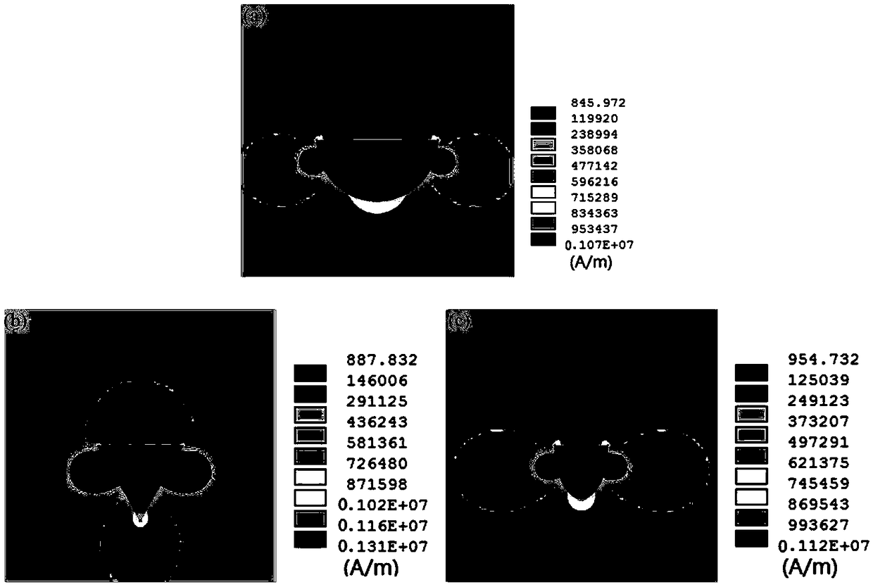
[0058] Figure 4 As shown, in the columnar combined magnetic medium of this embodiment, the magnetic medium is sequentially provided with a non-magnetic part 1 and a magnetic part 2 along the flow direction of the pulp, and the non-magnetic part 1 and the magnetic part 2 are fixedly connected to each other. In this embodiment, both the non-magnetic-permeable part 1 and the magnetic-permeable part 2 are semi-cylindrical (semi-circular in cross section, with a diameter of 2 mm).

[0059] In this embodiment, the non-magnetic part 1 is made of a non-magnetic material (such as SUS304), and the magnetic part 2 is made of a magnetic material (such as engineering pure iron).

[0060] In other embodiments, the shape of the cross-section of the non-magnetic portion 1 can also be a semi-ellipse or a semi-diamond. like Figure 5 As shown, the major axis of the semi-ellipse is 2mm; Image 6 As shown, the minor axis of the semi-ellipse is 2mm; as Figure 7 As shown, the side length of t...

Embodiment 2

[0075] like Figure 10 As shown, in the columnar combined magnetic medium of this embodiment, the magnetic medium is sequentially provided with a non-magnetic part 1 and a magnetic part 2 along the flow direction of the pulp, and the non-magnetic part 1 and the magnetic part 2 are fixedly connected to each other. In this embodiment, the cross-section of the non-magnetic portion 1 and the magnetic portion 2 is a semi-diamond (in this embodiment, the angle between the two sides of the semi-diamond is 60°, but it is not limited to the situation in this embodiment, and can be made according to the actual situation. Requirements change), the side length is 2mm.

[0076] In this embodiment, the non-magnetically permeable part 1 is made of non-magnetically permeable material (eg SUS304), and the magnetically permeable part 2 is made of magnetically permeable material (eg SUS430).

[0077] In other embodiments, the shape of the cross section of the non-magnetic portion 1 can also be ...

Embodiment 3

[0080] like Figure 14 As shown, in the columnar combined magnetic medium of this embodiment, the magnetic medium is sequentially provided with a non-magnetic part 1 and a magnetic part 2 along the flow direction of the pulp, and the non-magnetic part 1 and the magnetic part 2 are fixedly connected to each other. In this embodiment, the cross-sections of the non-magnetic part 1 and the magnetic part 2 are semi-elliptical, the minor axis of the semi-ellipse of the magnetic part 2 is 2mm, and the long axis is 3mm, and the short axis of the non-magnetic part 1 is 2mm.

[0081] In this embodiment, the non-magnetically permeable part 1 is made of non-magnetically permeable material (eg SUS304), and the magnetically permeable part 2 is made of magnetically permeable material (eg SUS430).

[0082] In other embodiments, the shape of the cross-section of the non-magnetic portion 1 can also be other forms of semi-ellipse, semi-diamond or semi-circle. like Figure 15 As shown, the maj...


PUM


Abstract

The invention discloses combined magnetic media, further provides a magnetic medium pile, and further provides an intermittent magnetic separation device comprising the magnetic medium pile, a methodfor mineral separation of the intermittent magnetic separation device, a vertical ring high-gradient magnetic separator and a method for mineral separation of the vertical ring high-gradient magneticseparator correspondingly. The magnetic media are in a column or ring shape, and are sequentially provided with non-magnetic-conduction parts and magnetic-conduction parts in the ore pulp flowing direction; the non-magnetic-conduction parts and the magnetic-conduction parts are fixedly connected with each other, and the edges of the non-magnetic-conduction parts are each of a smooth hook face structure or a sharp corner structure for flow guiding; the magnetic medium pile comprises the magnetic media which are parallelly arranged at intervals; and by controlling shapes of the non-magnetic-conduction parts and the magnetic-conduction parts, the magnetic media are matched with the non-magnetic-conduction parts and the magnetic-conduction parts in texture to generate flow fields and magneticfields facilitating magnetic mineral collecting better, the acting effect of the magnetic media can be further reinforced, and the weakly magnetic mineral collecting efficiency is improved while mechanical inclusions are reduced or eliminated.

Description

technical field [0001] The invention belongs to the field of mineral separation equipment, and in particular relates to a magnetic medium, a magnetic medium stack, a magnetic separator and a magnetic separation method. Background technique [0002] Weak magnetic mineral resources mainly include hematite, limonite, siderite, ilmenite, wolframite, manganese ore and tantalum-niobium rare earth ore. These weakly magnetic mineral raw materials have played an important role in my country's economic development. High-gradient magnetic separation is a common method for processing weak magnetic minerals. However, due to the mechanical inclusion of gangue minerals in the separation process, it is difficult to obtain qualified weak magnetic mineral concentrate products in a single high-gradient magnetic separation operation. High-gradient magnetic separation is used for roughing, and the obtained rough concentrate is then flotation-selected to obtain the final concentrate product. The...

Claims


Application Information

Patent Timeline
Patent Type & Authority Applications(China)
IPC IPC(8): B03C1/031B03C1/00
CPCB03C1/002B03C1/031
Inventor 郑霞裕王毓华卢东方
Owner CENT SOUTH UNIV
Learn More