Multi-energy beam high-efficiency additive manufacturing method

An additive manufacturing and high-efficiency technology, which is applied in the field of multi-energy beam high-efficiency additive manufacturing, can solve the problems of no improvement in the forming efficiency of a single format, the inability to realize multiple scanning strategies, and reduce the overall forming efficiency. High phenomenon, improve the forming internal stress, improve the effect of forming quality

Active Publication Date: 2019-03-08
HUAZHONG UNIV OF SCI & TECH
View PDF9 Cites 14 Cited by
  • Summary
  • Abstract
  • Description
  • Claims
  • Application Information

AI Technical Summary

Problems solved by technology

[0003] The patent "A high-efficiency forming equipment and method for laser selective melting", application number "201611199926.3" proposes a method based on two forming cylinders and a single laser beam alternately forming two components, shortening the time for powder spreading, thereby improving the forming efficiency of equipment However, the rotating forming cylinder platform reduces the overall forming efficiency. On the other hand, the rotation of the forming cylinder platform may affect the quality of powder coating
The patent "multi-beam additive manufacturing", application number "201680034015.7" proposes a multi-beam additive manufacturing technology method, which expands the overall forming area by increasing the number of laser beams, thereby improving the forming efficiency of the equipment. However, the forming efficiency of a single area is still no improvement
The patent "Additive Manufacturing Device Using Electron Beam-Laser Composite Scanning", application number "201510104702.9" proposes to use multiple electron beam and laser beam composite scanning methods to realize additive manufacturing, which improves the efficiency of forming equipment and expands the forming area. However, each electron beam and laser beam can only form the corresponding area, and each energy beam cannot irradiate the entire forming area, and the various scanning strategies mentioned above cannot be realized; the patent "Laser selective melting based on four laser double stations SLM equipment and processing method", application number "201310670777.4", proposes to improve the forming efficiency of large-size components by combining low-power scanning of several layers of contours and high-power forming single-layer solids, because the high and low power used in this method is The step-by-step scanning method does not scan the components at the same time, which limits the further improvement of the forming efficiency to some extent

Method used


Image

  • Multi-energy beam high-efficiency additive manufacturing method
  • Multi-energy beam high-efficiency additive manufacturing method
  • Multi-energy beam high-efficiency additive manufacturing method

Examples


example 1

[0032] Example 1: Design of multi-set galvanometer optical path system with full energy beam coverage

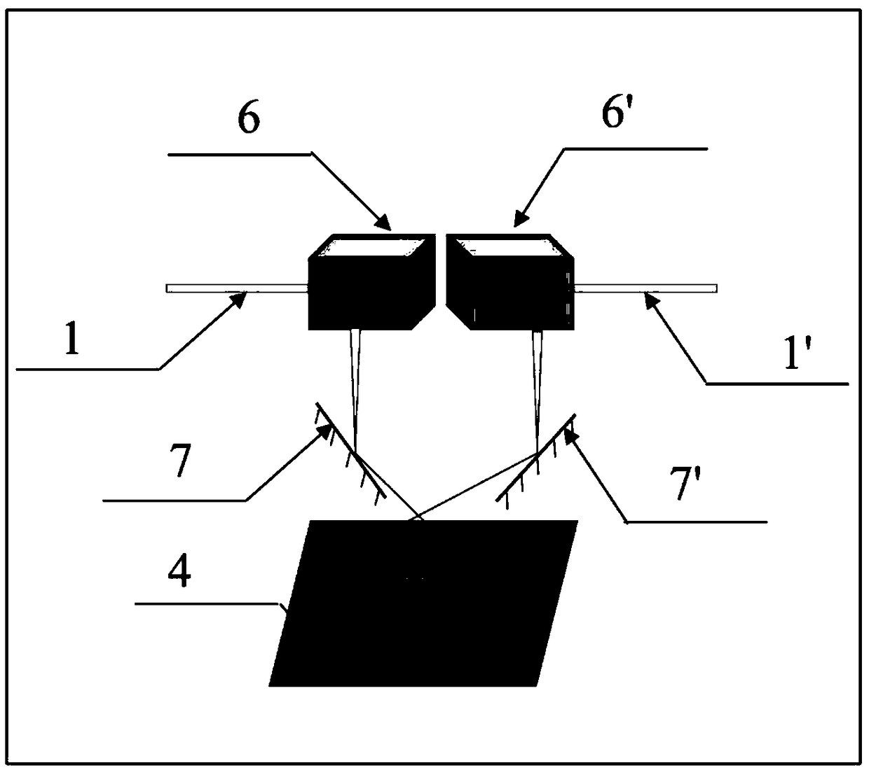
[0033] Such as figure 2 As shown, in this example, two laser beams 1 and 1', two galvanometer systems 6 and 6', and two reflectors 7 and 7' are used to realize the scanning mode in which the energy beams can cover the whole frame.

[0034] The working principle of the optical path system is that two beams of light 1 and 1' respectively enter the respective galvanometer systems 6 and 6' from the side, and emit beams from the bottom of the galvanometer.

[0035] The light beams emitted from the bottom of the galvanometer pass through the reflectors 7 and 7' respectively, and finally directly irradiate the entire forming area.

[0036] The light beam mainly realizes the direction change of the incident beam through the vibrating mirror and the reflecting mirror, and the rotation of the reflecting mirror and the organic combination of the vibrating mirror further expand the co...

example 2

[0037] Example 2: Design of a galvanometer optical path system with full coverage of the energy beam II

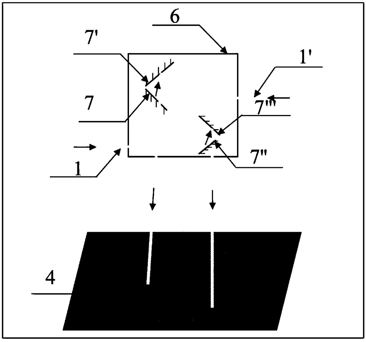
[0038] Such as image 3 As shown, this example designs a new type of galvanometer optical path system, so that each energy beam can irradiate the entire forming area.

[0039] The vibrating mirror system includes a vibrating mirror 6, and two sets of reflecting mirrors (7 and 7', 7" and 7'") are integrated.

[0040] Two sets of reflective mirrors are respectively located at the upper part and the lower part of the vibrating mirror system, and two laser beams 1 and 1' are respectively injected into the vibrating mirror system from both sides.

[0041] After passing through the corresponding reflector lens groups respectively, through the rotation of the reflector and the organic mutual cooperation, the two beams of light are emitted from the bottom of the vibrating mirror.

[0042] Based on the existing vibrating mirror system, this design method adopts two sets of reflec...

example 3

[0043] Example 3: Powder-spreading multi-laser beam interval scanning

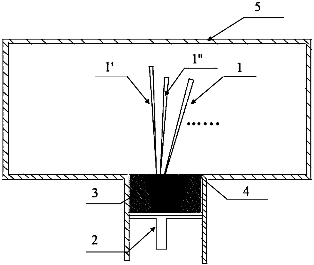
[0044] Such as Figure 4 As shown, in this example, two laser beams are used for rapid processing of the component at the same time, and the powder supply method adopts the powder spreading method.

[0045] Before the two laser beams are processed, the protective gas is passed into the forming cavity 5 to reduce the oxygen content in the forming area, so as to ensure the quality of the forming and the safety of the processing process.

[0046] On the surface of the working platform 4, the laser beams 1 and 1' first scan and process the adjacent tracks of the current layer, and after scanning the corresponding single track, the corresponding laser beams 1 and 1' scan and process the other two tracks at the same time , until the current layer is completely scanned by the energy beam.

[0047] The 2 laser beams work independently without affecting each other until the current layer is completely melted.

...


PUM


Abstract

The invention discloses a multi-energy beam high-efficiency additive manufacturing method. The multi-energy beam high-efficiency additive manufacturing method is characterized in that a plurality of energy beams exist in one surface, each energy beam can irradiate an entire forming region, the energy beams perform mutually independent scanning and / or mutually matched scanning on a to-be-formed region, and raw material powder is formed in the to-be-formed region. According to the multi-energy beam high-efficiency additive manufacturing method, scanning processing is carried out through the plurality of energy beams, scanning strategies of more varieties can be achieved, forming efficiency of equipment can be improved, microscopic structures of components can be regulated, forming internal stress is improved, and forming quality of the components is improved.

Description

technical field [0001] The invention belongs to the technical field of additive manufacturing, and more specifically relates to a multi-energy beam high-efficiency additive manufacturing method. Background technique [0002] Metal Additive Manufacturing (MAM) is the most important branch of additive manufacturing technology. It uses metal powder / wire as raw material, high-energy beam (laser / electron beam / arc / plasma beam, etc.) A new technology that melts and accumulates materials layer by layer to manufacture high-performance metal components. It has the advantages of short forming cycle, high utilization rate of raw materials, and the ability to form components with arbitrary complex shapes. Widely used in aerospace, automobiles, military weapons, biomedical and other fields. Nevertheless, with the rapid development of aerospace technology and weaponry, higher requirements are placed on the forming efficiency of metal additive manufacturing technology. [0003] The pate...

Claims


Application Information

Patent Timeline
Patent Type & Authority Applications(China)
IPC IPC(8): B22F3/105B33Y10/00
CPCB33Y10/00B22F10/00B22F12/45B22F12/49B22F10/28B22F12/44B22F10/366B22F10/362Y02P10/25
Inventor 王泽敏孟梁黄文普靖冠乙曾晓雁
Owner HUAZHONG UNIV OF SCI & TECH
Why Eureka
Try Eureka