
Passive wireless temperature sensor

A temperature sensor, passive wireless technology, applied in the field of wireless sensing, to achieve the effect of solving failure

Pending Publication Date: 2019-03-08
JIANGNAN UNIV
View PDF0 Cites 5 Cited by
  • Summary
  • Abstract
  • Description
  • Claims
  • Application Information

AI Technical Summary

Problems solved by technology

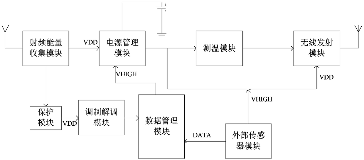
[0005] Aiming at the deficiencies of the prior art above, the present invention provides a passive wireless temperature sensor used in a special environment; the passive wireless sensor of the present invention can be applied to temperature measurement in harsh environments, and it can not only meet some strict requirements, Moreover, the problem of power supply is solved, no power supply is needed in the environment to be tested, and data transmission adopts wireless transmission, which makes the wiring and structure of the whole system very simple

Method used


Image

  • Passive wireless temperature sensor
  • Passive wireless temperature sensor
  • Passive wireless temperature sensor

Examples


Embodiment 1

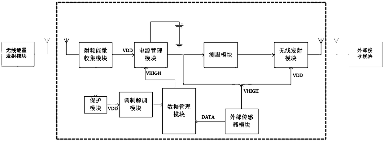
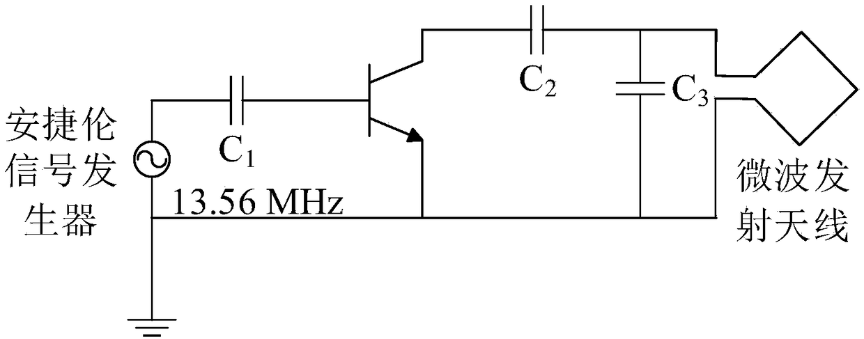
[0049] Such as figure 2 As shown, a passive wireless temperature sensor in this embodiment includes a microwave receiving antenna, a signal receiving antenna, a radio frequency energy collection module, a protection module, a power management module, a modulation and demodulation module, a data management module, a temperature measurement module, and an external sensor module , Wireless transmitting module, wireless energy transmitting module, receiving module, signal transmitting antenna, microwave transmitting antenna, auxiliary power supply. The output terminal of the microwave receiving antenna is connected to the input terminal of the radio frequency energy collection module; the output terminal of the radio frequency energy collection module is connected to the input terminal of the protection module and the power management module; the output terminal of the protection module is connected to the input terminal of the modem module; the power management module The output...

Embodiment 2

[0067] In this embodiment, a constant temperature and humidity chamber is used to simulate a confined space environment, and the passive wireless temperature sensor described in Embodiment 1 is used for temperature collection. The collection process and results are as follows:

[0068] The radio frequency energy collection module of the present invention, protection module, power supply management module, modulation and demodulation module, data management module, temperature measurement module, external sensor module, wireless transmission module, auxiliary power supply are arranged in constant temperature and humidity box, constant temperature and humidity The inside of the box is a closed environment. Set the temperature change range of the constant temperature and humidity box to 45-100°C, the change time is 15 minutes, and the humidity is set to 45%. The wireless energy transmission module is set at a place 60CM away from the constant temperature and humidity box. The modu...


PUM


Abstract

The invention discloses a passive wireless temperature sensor and belongs to the field of wireless sensing. The passive wireless temperature sensor comprises a receiving antenna, a radio frequency energy collecting module, a protection module, a power management module, a modulation and demodulation module, a data management module, a temperature measurement module, an external sensor module, a wireless transmitting module, a transmitting antenna, an auxiliary power supply, a wireless energy transmitting module and a receiving module. The radio frequency energy collecting module and the wireless energy transmitting module are adopted to generate current through an electromagnetic induction principle to provide power to a circuit in environment to be tested, the problem of power supply of the circuit in a special environment is solved, a schottky diode is used as a temperature measurement component, a schottky diode adopting a special material is used as a temperature-collecting element, the schottky diode has the characteristics of high temperature resistance, high voltage and high frequency, so that the problem that a common sensor fails in the special environment is solved; no direct power supply unit and data transmission line exists in the circuit of the environment to be tested, and the passive wireless temperature sensor is simple in structure and convenient to arrange.

Description

technical field [0001] The invention relates to a passive wireless temperature sensor, which belongs to the field of wireless sensing. Background technique [0002] Temperature sensors are widely used in agricultural production, microelectronics process research and development and production, aerospace and other fields. However, in harsh environments, such as high temperature, airtight, high-speed rotation, etc., accurate temperature measurement is still a very challenging problem. Active wired temperature sensing technology has problems such as power supply replacement, maintenance costs, potential safety hazards, temperature measurement limitations, large size, and inconvenient layout. [0003] Studies have shown that the forward current of Schottky diodes is constant, and within a certain temperature range, there is a linear relationship between the forward voltage drop across the device and the temperature change. Using this characteristic, Schottky diodes can be used ...

Claims


Application Information

Patent Timeline
Patent Type & Authority Applications(China)
IPC IPC(8): G01K7/01G01K1/02G08C17/02G01K1/024
CPCG08C17/02G01K1/02G01K1/024G01K7/00G01K7/01
Inventor 姜岩峰许超
Owner JIANGNAN UNIV
Learn More