Channel phase alignment circuit and method

A phase alignment and channel technology, applied in synchronous signal speed/phase control, electrical components, digital transmission systems, etc., can solve the problem of large serial-to-parallel conversion delay, uncertain parallel clock phase offset, and multi-channel data transmission merging Deal with difficulties and other problems to achieve the effects of good precision control, reduced serial-to-parallel conversion delay, good process portability and flexibility

Active Publication Date: 2019-03-08
成都华大九天科技有限公司
View PDF8 Cites 4 Cited by
  • Summary
  • Abstract
  • Description
  • Claims
  • Application Information

AI Technical Summary

Problems solved by technology

Although the phase offset of the serial data stream between channels can be determined and kept relatively small through a certain sending-end technology and channel routing matching, but because each channel at the receiving end works independently, after the data is converted from serial to parallel, the parallel data The word boundary is uncertain, and the phase offset of the parallel clock is also uncertain, such as Figure 9 As shown, this makes it difficult for multiple data transmissions to be merged and processed at the receiving end
[0004] The traditional multi-way alignment technology introduces buffers on the parallel clock and data sides. After accessing multi-shot data, the sliding window is moved based on a specific code pattern, and the data is aligned and then moved out to form multi-way data alignment and word boundary determination. A very serious problem with the method is that the data cache needs at least two beats and works in the low-speed clock domain. This method has a large delay in serial-to-parallel conversion, and the low-speed operation will cause the aligned data to be wrong by a big beat, which is very important for Some demanding digital signal processing systems are unacceptable

Method used


Image

  • Channel phase alignment circuit and method
  • Channel phase alignment circuit and method
  • Channel phase alignment circuit and method

Examples


Embodiment Construction

[0041] The preferred embodiments of the present invention will be described below in conjunction with the accompanying drawings. It should be understood that the preferred embodiments described here are only used to illustrate and explain the present invention, and are not intended to limit the present invention.

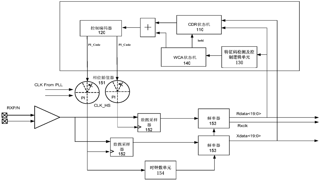
[0042] figure 1 It is a structural block diagram of a channel phase alignment circuit according to the present invention, such as figure 1 As shown, the channel phase alignment circuit of the present invention includes: a CDR state machine 110, a control encoder 120, a signature detection and control logic unit 130 and a WCA state machine 140, wherein,

[0043] The CDR state machine 110 is used for the clock and data recovery control algorithm to obtain the phase correspondence between the high-speed sampling clock and the data. Among them, the algorithm includes operations such as voting and filtering.

[0044] Preferably, the high-speed serial data enters the ...


PUM


Abstract

The invention provides a channel phase alignment circuit, comprising: a data receiving end, a CDR state machine, a control encoder, a feature code detection and control logic unit, and a WCA state machine, wherein the data receiving end receives high-speed serial data, performs sampling and serial-to-parallel conversion on the serial data, and generates a parallel clock; the CDR state machine is used for performing recovery control of a clock and data, and obtaining a phase corresponding relationship between a high-speed sampling clock and the data; the control encoder is used for converting the phase corresponding relationship into a control code of a high-speed clock interpolator; the feature code detection and control logic unit is used for monitoring a training feature code pattern ina serial data stream; and the WCA state machine is used for calculating a phase and a word boundary of the data, and switching a CDR loop to a WCA loop for phase alignment after the training feature code is detected for multiple times and has the same phase information. The invention further provides a channel phase alignment method, which can be used for performing accurate data word boundary alignment.

Description

technical field [0001] The invention relates to the technical field of integrated circuits, in particular to a channel phase alignment circuit and method. Background technique [0002] With the development of electronic industry technology, especially in the development of transmission interface, the data bandwidth is getting higher and higher, the speed of traditional parallel interface can no longer meet the demand, replaced by faster serial interface, serial data communication can Save connection resources, have small requirements for signal amplitude, and small crosstalk between signals, high transmission speed, widely used in various communication and consumer serial standards such as Ethernet, hard disk data transmission, high-definition image transmission, etc. . With the continuous expansion of various applications, the demand for data bandwidth is doubling year by year. Although the serial data rate of a single channel is continuously increasing, it cannot meet the...

Claims


Application Information

Patent Timeline
IPC IPC(8): H04L7/04H04L7/00
CPCH04L7/0025H04L7/0079H04L7/041
Inventor 唐重林刘寅
Owner 成都华大九天科技有限公司
Why Eureka
Try Eureka