High-temperature vacuum evaporation and ionization film coating device and operating method thereof

A high-temperature vacuum and coating device technology, which is applied in vacuum evaporation coating, ion implantation coating, sputtering coating, etc., to achieve the effect of increasing the applicable field, saving electric energy and improving safety

Pending Publication Date: 2019-03-12
台州市黄岩永恩模具表面处理厂
View PDF6 Cites 0 Cited by
  • Summary
  • Abstract
  • Description
  • Claims
  • Application Information

AI Technical Summary

Problems solved by technology

The evaporative coating in the prior art is only suitable for coating on non-metallic surfaces at low temperature, and there are no relevant reports on the equipment or method for coating workpieces at higher temperatures

Method used


Image

  • High-temperature vacuum evaporation and ionization film coating device and operating method thereof
  • High-temperature vacuum evaporation and ionization film coating device and operating method thereof
  • High-temperature vacuum evaporation and ionization film coating device and operating method thereof

Examples


Embodiment 1

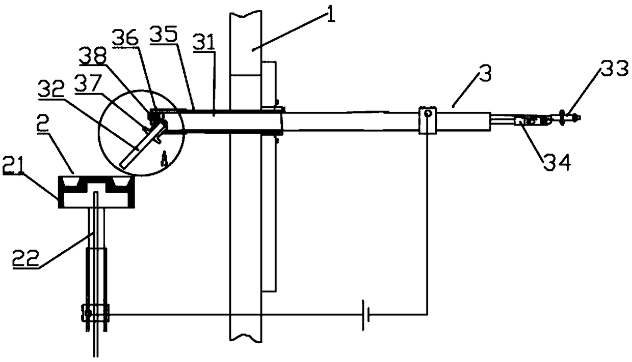
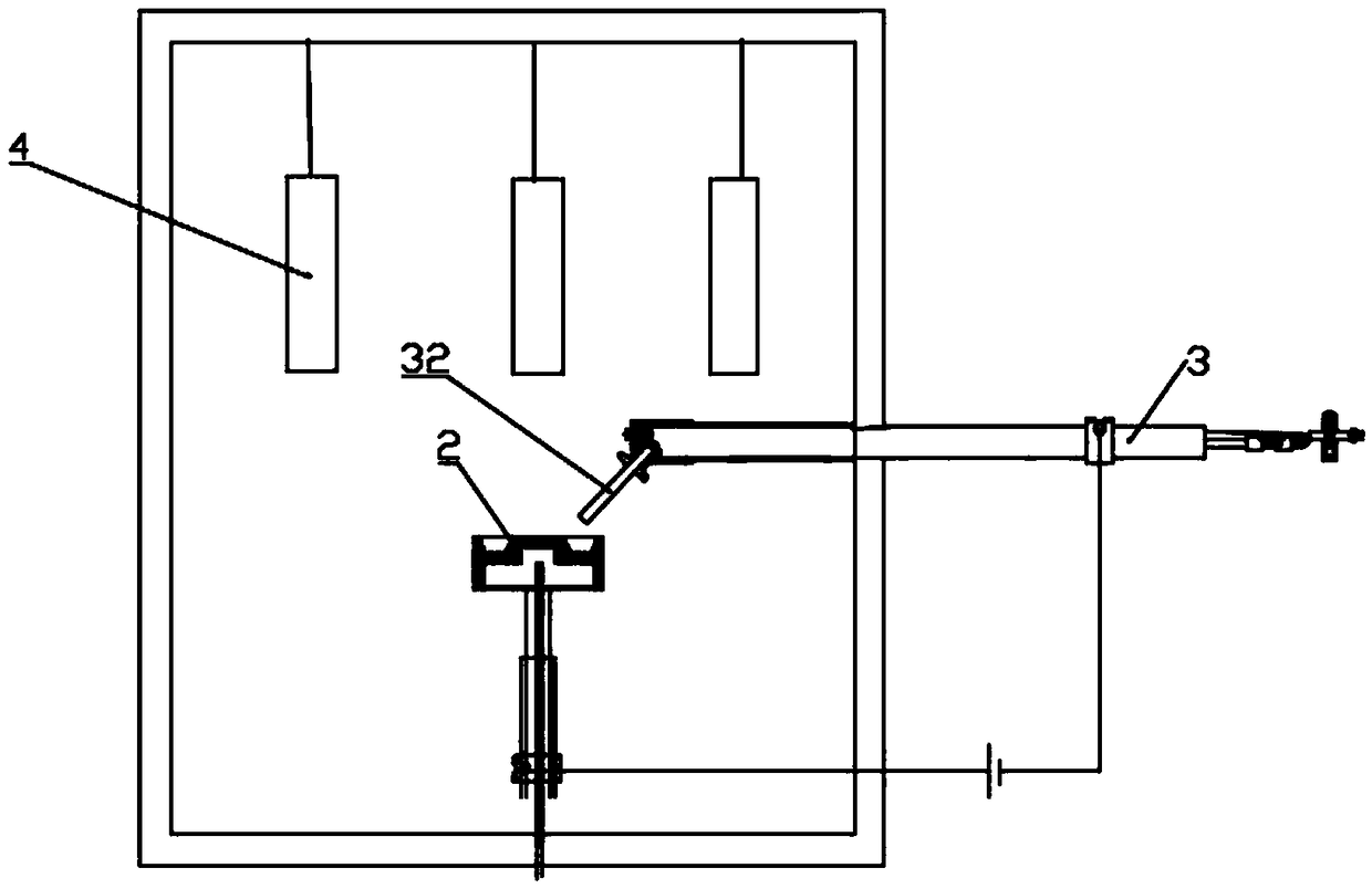
[0030] Such as Figure 1-3 As shown, the high-temperature vacuum evaporation ionization coating device includes a high-temperature vacuum-sealed body of furnace 1, and the inside of the body of furnace 1 is hung with parts 4 to be coated such as tools, metals, molds, etc. to be coated; the bottom of the parts 4 to be coated An evaporation source 2 is provided, and the inside of the evaporation source 2 is equipped with a plated metal. The furnace body of the furnace body 1 is provided with an electron gun 3 whose end extends into the interior of the furnace body 1, and the electron beam emitted by the electron gun 3 is injected into the evaporation source 2 to evaporate the coating metal;

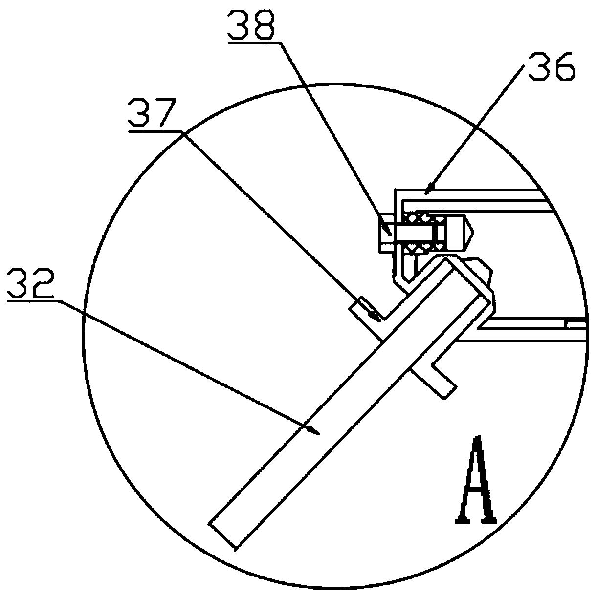
[0031] The electron gun 3 includes a metal sleeve 31 and a hollow tantalum tube 32 capable of self-sustaining discharge; one end of the hollow tantalum tube 32 is conductively connected to the end of the metal sleeve 31 through a fixed lock nut 37 made of molybdenum metal material, and the ...

Embodiment 2

[0033] On the basis of Embodiment 1, the pipe body of the metal sleeve 31 is provided with an insulating sleeve 35 for insulation between the metal sleeve 31 and the furnace body 1, and the end of the metal sleeve 31 located inside the furnace body 1 A protective sleeve 36 not in contact with the metal sleeve 31 is provided. The metal sleeve 31 is made of copper; the gas conduit 33 is made of copper; the hollow tantalum tube 32 is a hollow tantalum tube; the evaporation source 2 is a crucible 21 loaded with at least one coating metal ; The insulating sleeve 35 is a glass tube; the protective sleeve 36 is made of metallic copper.

Embodiment 3

[0035] On the basis of Embodiment 1, a cooling circuit 34 parallel to the gas duct 33 is also provided in the metal sleeve 31 . The cooling circuit 34 is used for cooling to prevent the damage of the electron gun 3 caused by the breakdown of the metal conduit caused by the internal temperature; cooling to prevent the constituent metals of the crucible 21 from evaporating and causing damage to the crucible 21 .

[0036] The junction of the electron gun 3 and the furnace body 1 or the front and rear adjacent areas of the junction are provided with a sealed structure.


PUM


Abstract

The invention discloses a high-temperature vacuum evaporation and ionization film coating device and an operating method thereof, and relates to the technical field of film coating. The high-temperature vacuum evaporation and ionization film coating device comprises a high-temperature vacuum sealed furnace body, an evaporation source arranged inside the furnace body, and an electronic gun, one endof which extends into the furnace body, wherein an electron beam emitted by the electronic gun is injected into the evaporation source, so that coating metal is evaporated; the electronic gun comprises a metal sleeve, and a hollow tantalum tube which can be self-sustained to discharge power; a fixed locking nut for connecting the hollow tantalum tube to the metal sleeve in a conduction mode is further arranged between the hollow tantalum tube and the metal sleeve; a gas through tube for introducing in working gas is inserted at a gas inlet of the metal sleeve; and the evaporation source is separately connected with a positive electrode and a negative electrode of a power supply through the electronic gun. The high-temperature vacuum evaporation and ionization film coating device expands the use range of the electronic gun, increases the applicable field of the evaporated functional coating, and greatly improves ionization efficiency of the working gas.

Description

technical field [0001] The invention relates to the technical field of coating, in particular to a high-temperature vacuum evaporation ionization coating device and an operating method thereof. Background technique [0002] In the prior art, the technology of producing thin film materials by physical methods, the atoms of the material are separated from the heating source in the vacuum chamber and hit the surface of the object to be plated, and a functional coating is plated on the surface of the material. This technology was first used to produce optical lenses, such as nautical telescope lenses. The evaporative coating in the prior art is only suitable for coating non-metallic surfaces at low temperatures, and there is no related report on equipment or methods for coating workpieces at higher temperatures. Contents of the invention [0003] In order to solve the technical problems in the prior art, the invention provides a high-temperature vacuum evaporation ionization ...

Claims


Application Information

Patent Timeline
IPC IPC(8): C23C14/30
CPCC23C14/30
Inventor 莫申波周卫星
Owner 台州市黄岩永恩模具表面处理厂
Why Eureka
Try Eureka