Smart emergency control system

An emergency control and intelligent technology, applied in transmission systems, closed-circuit television systems, instruments, etc., can solve the problem of prolonging the time for abnormal situations to reach the supervision terminal, management personnel being unable to deal with emergency events in time, and data center difficult to control instructions to the controlled terminal. and other problems to achieve the effect of extending the time

Inactive Publication Date: 2019-03-12
ZDST COMM TECH CO LTD
View PDF4 Cites 14 Cited by
  • Summary
  • Abstract
  • Description
  • Claims
  • Application Information

AI Technical Summary

Problems solved by technology

[0005] In view of this, the embodiment of the present invention provides an intelligent emergency control system to solve the problem that in the prior art, it is difficult for the data center to issue control instructions to the controlled termi

Method used


Image

  • Smart emergency control system
  • Smart emergency control system

Examples


Embodiment 1

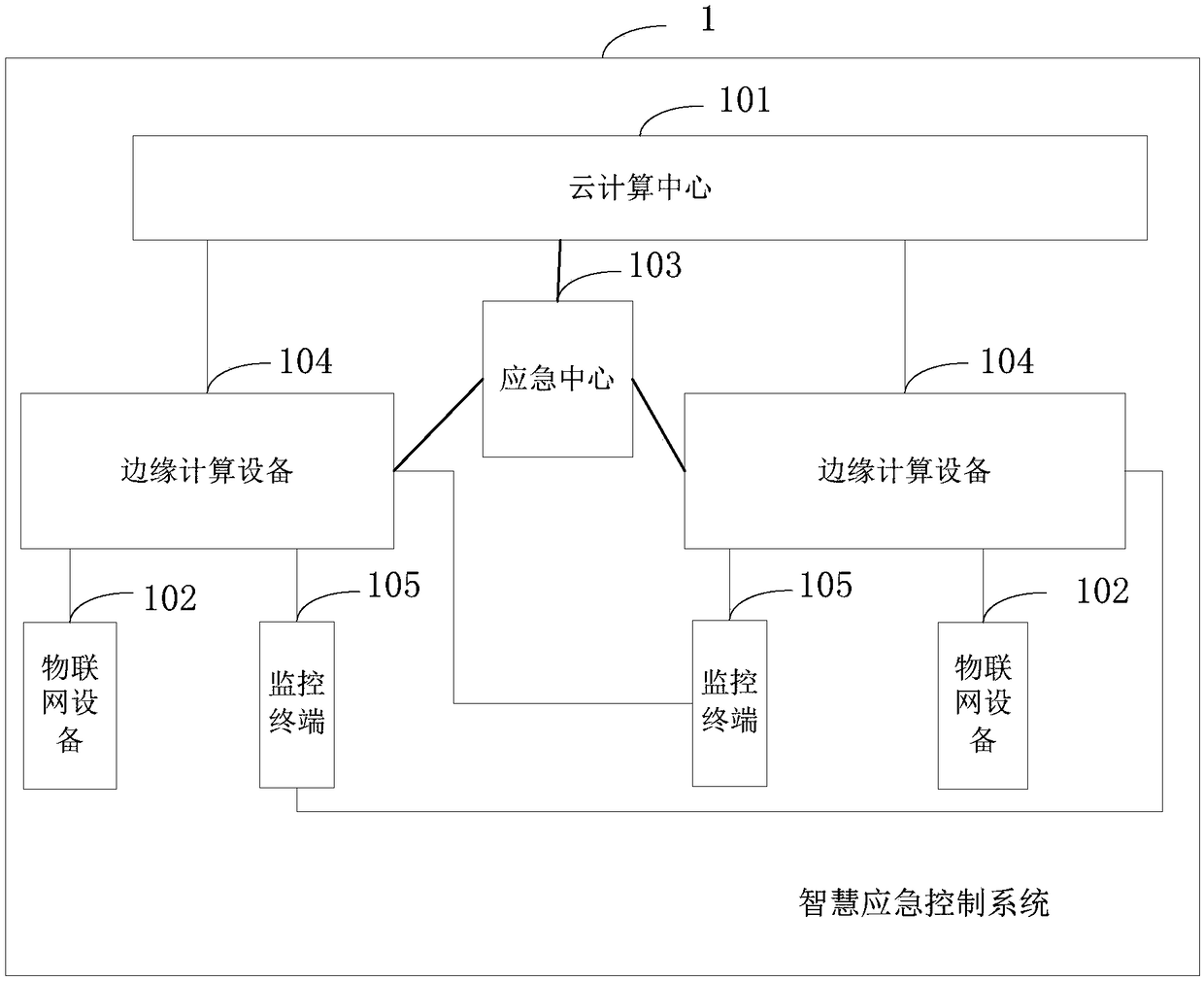
[0034] Such as figure 1 As shown, this embodiment provides a smart emergency control system 1, which includes a cloud computing center 101, an Internet of Things device 102, an emergency center 103, at least two edge computing devices 104, and at least two monitoring terminals 105;

[0035] The cloud computing center 101 is connected to the edge computing device 104 and the emergency center 103 by wired network communication;

[0036] The IoT device 102 is connected in communication with the edge computing device 104; wherein, the IoT device 102 includes a smart sensor 1021, a network camera 1022, and a controlled terminal 1023;

[0037] The emergency center 103 communicates with the edge computing device 104;

[0038] The edge computing device 104 communicates with the monitoring terminal 105;

[0039] The edge computing device 104 is used to receive the monitoring data sent by the smart sensor 1021, perform risk analysis on the monitoring data, obtain analysis results, sen...

Embodiment 2

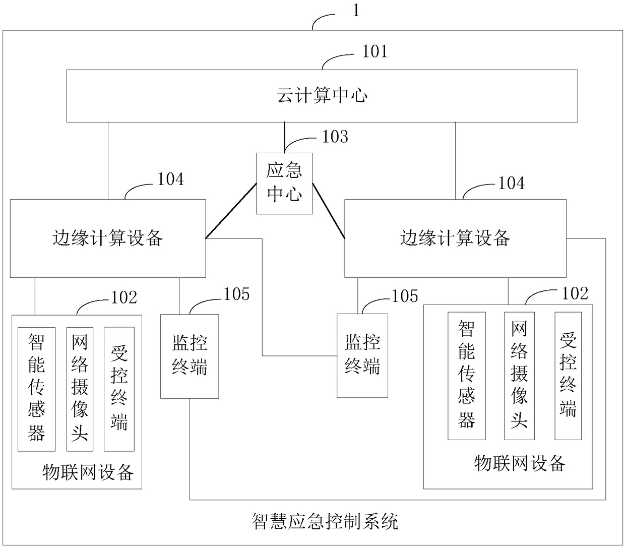
[0063] Such as figure 2 As shown, this embodiment provides a smart emergency control system 1 including a cloud computing center 101, an Internet of Things device 102, an emergency center 103, at least two edge computing devices 104, and at least two monitoring terminals 105;

[0064] The cloud computing center 101 is communicatively connected with the edge computing device 104, the emergency center 103 and the wired network;

[0065] The IoT device 102 is connected in communication with the edge computing device 104; wherein, the IoT device 102 includes a smart sensor 1021, a network camera 1022, and a controlled terminal 1023;

[0066] The emergency center 103 communicates with the edge computing device 104;

[0067] The edge computing device 104 communicates with the monitoring terminal 105;

[0068] The edge computing device 104 is used to receive the monitoring data sent by the smart sensor 1021, perform risk analysis on the monitoring data, obtain analysis results, se...


PUM


Abstract

The invention is applicable to the technical field of risk control, and provides a smart emergency control system, comprising a cloud computing center, an Internet of Things device, an emergency center, at least two edge computing devices, and at least two monitoring terminals, wherein the Internet of Things device is in communication connection with the edge computing devices, and the emergency center is in communication connection with the edge computing devices; the edge computing devices are in communication connection with the monitoring terminals for receiving monitoring data sent by smart sensors, performing risk analysis, sending analysis results to the monitoring terminals and sending the monitoring data to the cloud computing center; the cloud computing center is in wired networkcommunication connection with the edge computing devices and the emergency center for processing a non-real-time Internet of Things service request, storing the monitoring data, performing non-real-time analysis, and sending a non-real-time analysis result to the emergency center and/or the monitoring terminals; and the monitoring terminals perform risk early warning or display based on the analysis results and the non-real-time analysis result. The smart emergency control system provided by the invention reduces the response delay and the bandwidth cost and relieves the central cluster pressure.

Description

technical field [0001] The invention belongs to the technical field of risk control, in particular to an intelligent emergency control system. Background technique [0002] The existing intelligent emergency control system is an emergency control system in which a terminal with a sensor sends monitoring data to a data center, obtains abnormal conditions through cloud computing analysis, and then pushes the abnormal conditions to controlled terminals and supervisory terminals. [0003] However, because a large number of terminals will be connected to the Internet, an extremely large amount of data will be generated, and the sending and receiving of a large amount of data may cause I / O (input and output) bottlenecks between the data center and the terminals, the transmission rate will be greatly reduced, and even cause Great delay. [0004] Due to the uncontrollable downlink delay of the data center, it is difficult for the data center to issue control instructions to the con...

Claims


Application Information

Patent Timeline
IPC IPC(8): H04L29/08H04N7/18G08B21/24G08B25/08
CPCG08B21/24G08B25/08H04L67/025H04L67/14H04N7/18
Inventor 王元鹏
Owner ZDST COMM TECH CO LTD
Why Eureka
Try Eureka