
Die with roller inner rib rotating and extruding function and molding method thereof
A technology of rollers and molds, applied in the direction of metal extrusion molds, etc., can solve the problems of complex forming operation process, low forming efficiency, easy wrinkling forming pressure, etc., and achieve the effects of wide application range, improved efficiency, and improved forming accuracy
- Summary
- Abstract
- Description
- Claims
- Application Information
AI Technical Summary
Problems solved by technology
Method used
Image

Examples
Embodiment Construction
[0031] The present invention will be further described below in conjunction with the accompanying drawings and embodiments.
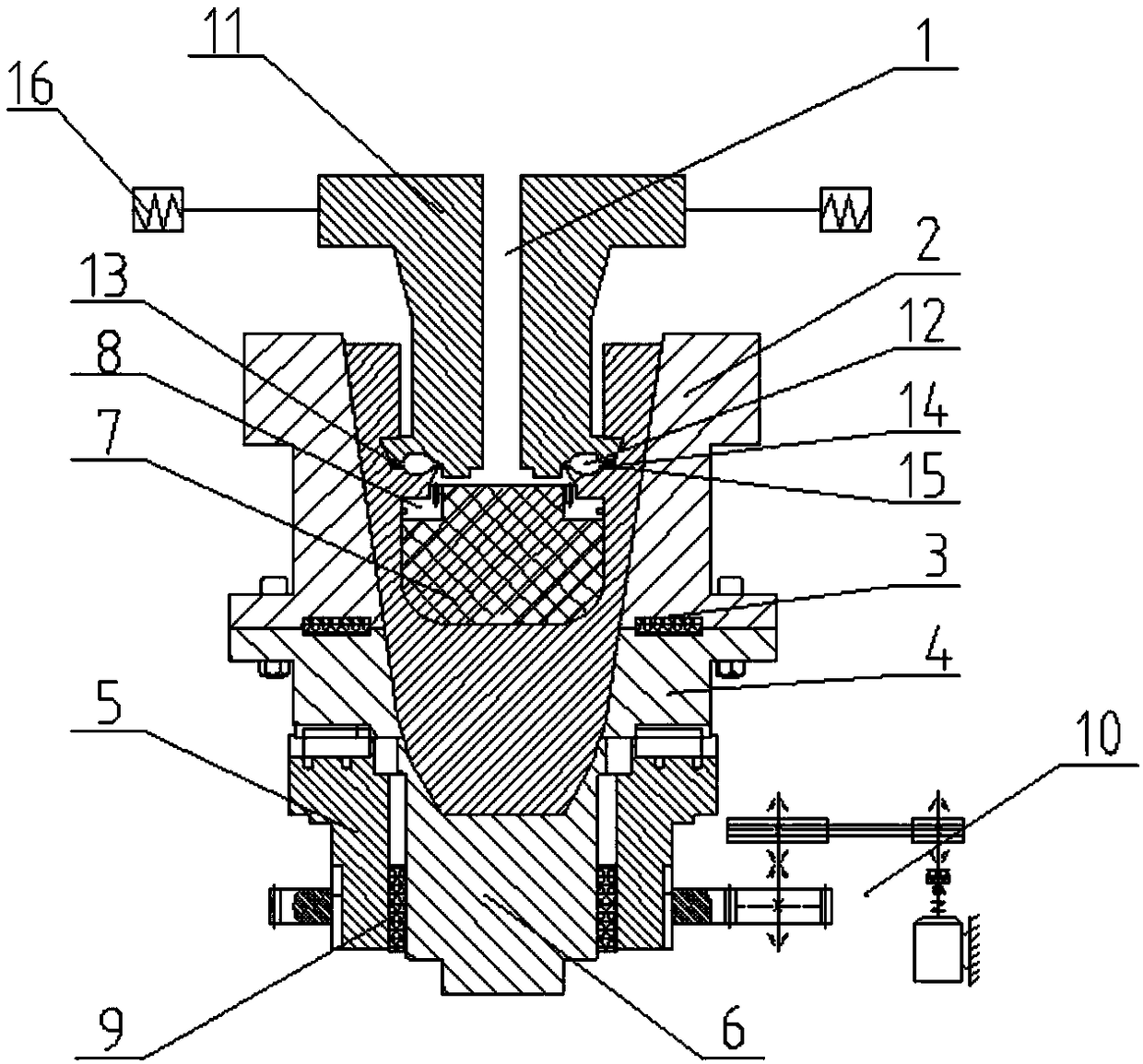
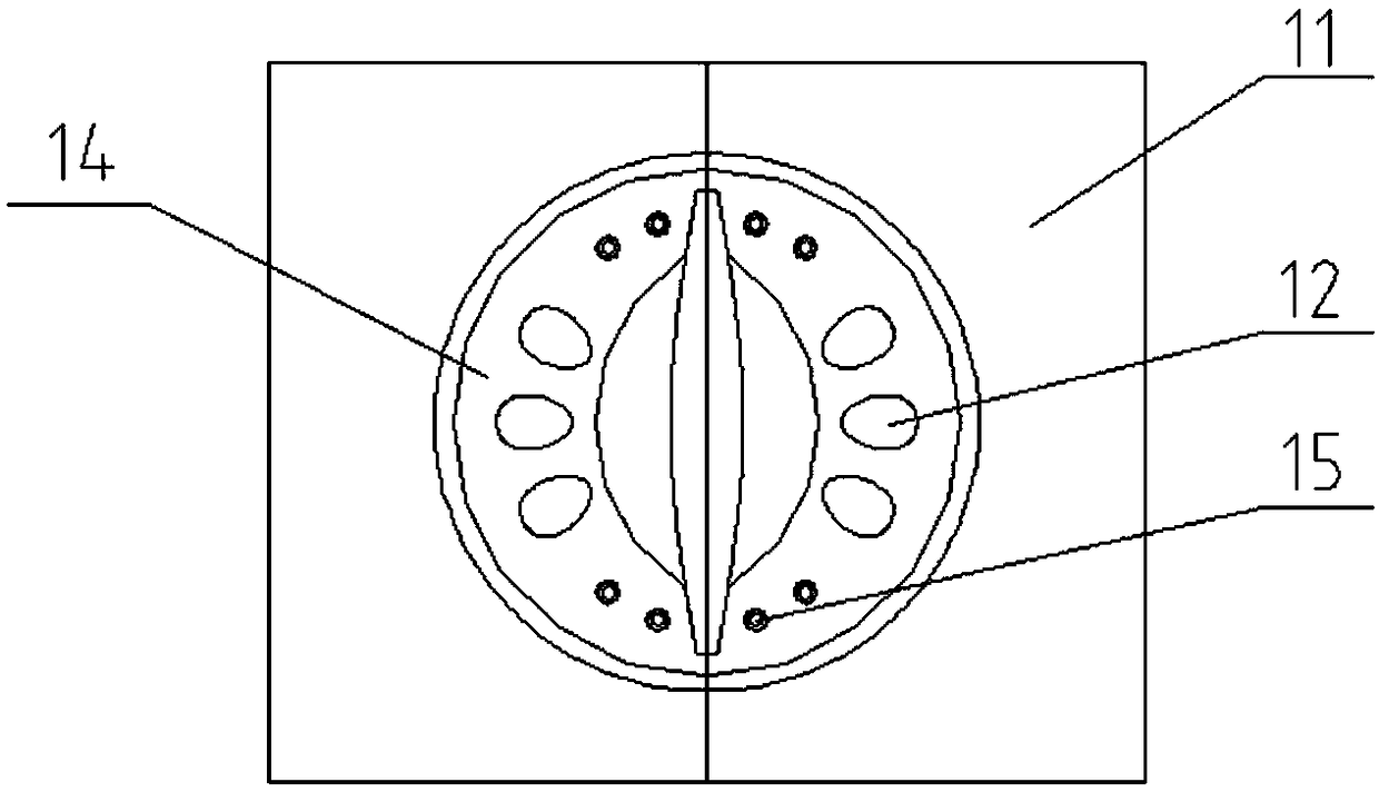
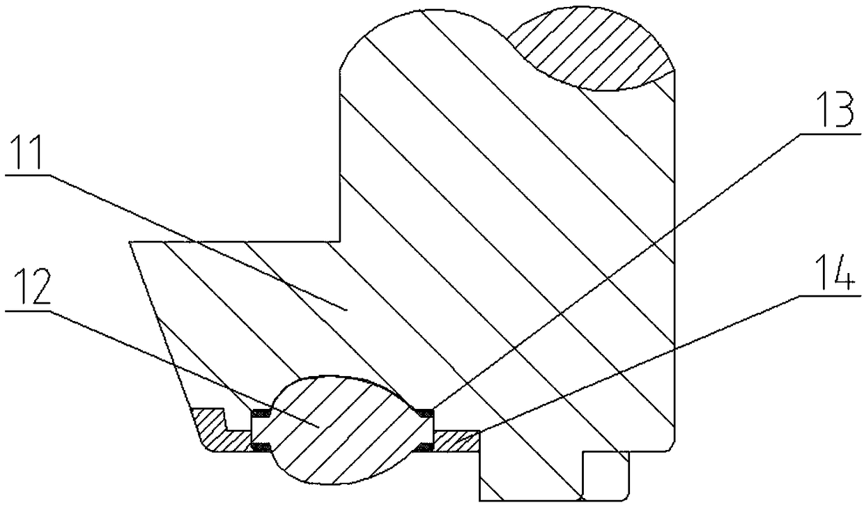
[0032] Such as figure 1 As shown, a mold with rollers in this embodiment for rotary extrusion of inner ribs includes a split punch 1, an upper die 2, a key 3, a lower die 4, a turntable 5, a tray 6, and a sand core lining 7 and a steel ring lining 8, the tray 6 is located at the bottom of the lower die 4 and is located in the tray hole set at the center of the turntable 5 and the outer surface of the tray 6 is connected with the tray hole of the turntable 5 through a sliding key 9, the lower die The bottom surface of 4 is connected with the turntable 5, the bottom surface of the upper die 2 is connected with the top surface of the lower die 4 by bolts, and the key 3 is located between the bottom surface of the upper die 2 and the top surface of the lower die 4 and is located In the keyway provided on the bottom surface of the upper die 2 and the top su...
PUM
 Abstract
Description
Claims
Application Information