
Full-automatic rolling composite molding machine for plastic sheet double-sided composite materials

A composite material and composite molding technology, which is applied in the direction of coiling strips, thin material processing, metal processing, etc., can solve the problems of high product cost, viscous aging failure of glue bonding layer, poor weather resistance of glue bonding layer, etc., to achieve Save the cost of plant space and equipment, reduce the amount of toxic substances, and improve the effect of product environmental protection

Inactive Publication Date: 2019-03-15
何浩然
View PDF0 Cites 2 Cited by
  • Summary
  • Abstract
  • Description
  • Claims
  • Application Information

AI Technical Summary

Problems solved by technology

The structure of this kind of composite device is relatively complicated, because the composite material is divided into two times, resulting in a longer equipment length and occupying more workshop space
The investment in equipment is relatively large, not only the plastic substrate extrusion molding machine, but also the compound machine, and the product cost is relatively high
And the resulting composite plastic sheet quality is relatively poor, mainly because there will be a glue bonding layer between the plastic base material and the decorative fabric, and the weather resistance of the glue bonding layer is relatively poor. After using for a period of time, the glue bonding layer Viscosity is prone to failure due to aging

Method used


Image

  • Full-automatic rolling composite molding machine for plastic sheet double-sided composite materials
  • Full-automatic rolling composite molding machine for plastic sheet double-sided composite materials
  • Full-automatic rolling composite molding machine for plastic sheet double-sided composite materials

Examples


Embodiment Construction

[0021] The technology will be further described below in conjunction with the accompanying drawings.

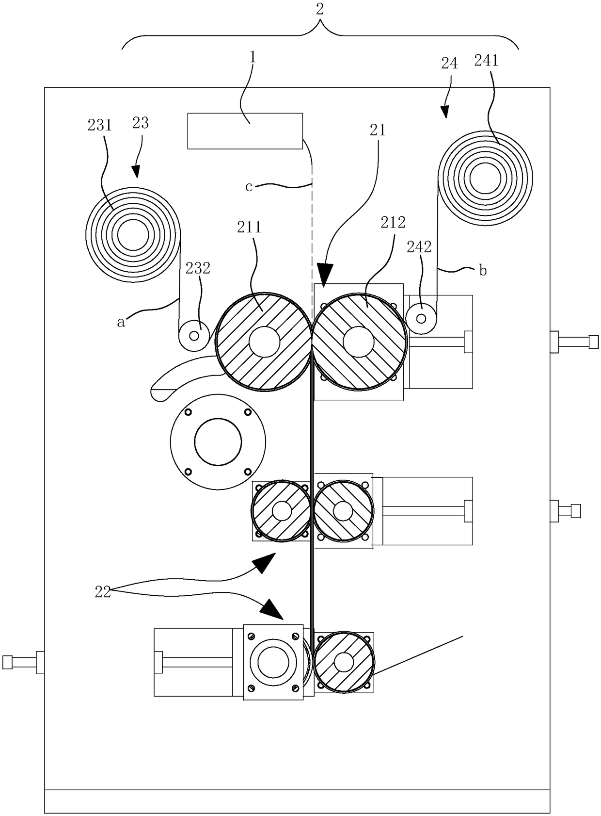
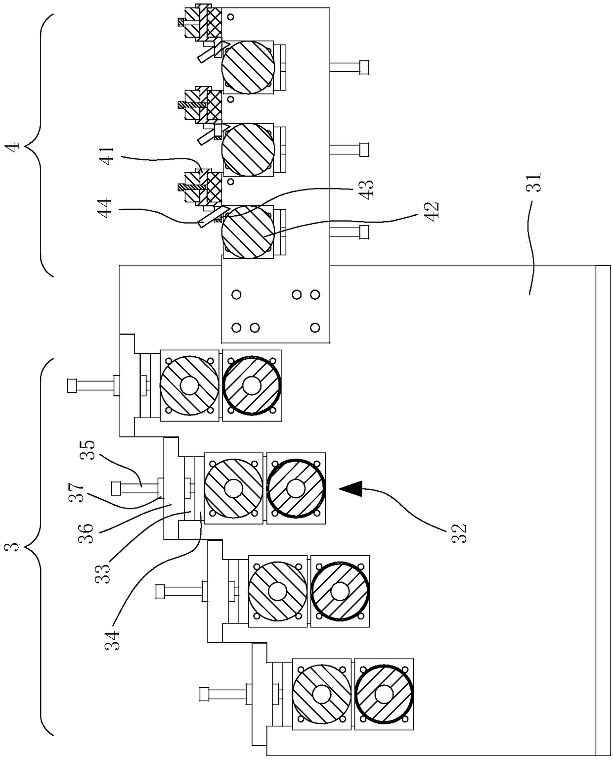
[0022] The fully automatic rolling compound molding machine of this embodiment includes a discharge port 1 connected to the extruder, a composite molding unit 2, a cooling unit 3, a cutting unit 4, a primary traction unit 5, a belt traction unit 6 and CNC punching unit 7, the discharge port 1 is set above the composite molding unit 2, and the rear of the composite molding unit 2 is sequentially arranged with a cooling unit 3, a cutting unit 4, a primary traction unit 5, a belt traction unit 6 and a CNC punching unit. The unit 7 and the composite molding unit 2 are composed of a pair of mold rolls 21, a pair of primary cooling rolls 22 and unwinding devices 23 and 24. Two sets of pairs of primary cooling rolls 22 are arranged in sequence directly below the pair of die rolls 21. After the mold roll pair 21 comes out, it is immediately cooled by two sets of primary cooling roll ...


PUM


Abstract

The invention discloses a full-automatic rolling composite molding machine for plastic sheet double-sided composite materials, and the machine includes a discharge port connected to an extruder, a compound molding unit, a cooling unit, a cutting unit, a belt traction unit and a numerical control punching unit, the discharging port is arranged above the composite molding unit, the cooling unit, thecutting unit, the belt traction unit and the numerical control punching unit are arranged at the rear of the composite molding unit in sequence, the composite molding unit cutting unit is composed ofa pair of mold rollers, a pair of primary cooling rollers and unwinding devices, the pair of mold rollers are left and right aligned, the discharge port is arranged above the pair of mold rollers, each forming roller of the pair of mold rollers is correspondingly provided with a set of unwinding device, the unwinding device releases the coil to the forming roller, and a free falling space for products is reserved between the belt traction unit and the numerical control punching unit.

Description

Technical field: [0001] The invention relates to a fully automatic rolling composite forming machine for double-sided composite materials of plastic sheets. Background technique: [0002] At present, the traditional production of plastic composite sheets is to extrude the plastic substrate on the extruder first, then convey the plastic sheet on the conveyor belt of the compound machine, and use the unwinding device to release the coil. During the process of conveying the plastic sheet and releasing the coil , or apply glue on the plastic sheet, or apply glue on the coil, and then pass through each functional roller, press and bond the coil on the upper surface of the plastic sheet, and then release another roll below Material, the same as compounding the aforementioned roll material, another roll material is compounded on the lower surface of the plastic sheet material. The structure of this composite device is relatively complicated, because the composite materials are div...

Claims


Application Information

Patent Timeline
IPC IPC(8): B29C65/02B29C65/78B29C48/25B26D7/28B65H20/02B26F1/40
CPCB29C65/02B26D7/28B26F1/40B29C65/78B29C66/0326B29C66/45B29C66/81B65H20/02
Inventor 何浩然
Owner 何浩然
Learn More