Gas sensor characteristic test system for multi-physical field coupling environment

A gas sensor and multi-physics technology, applied in the direction of material resistance, can solve the problems of increased resistance, reduced carrier number, and increased carrier drift path, achieving high uniformity, controllable direction, and good stability Effect

Inactive Publication Date: 2019-03-15
SOUTHWEST UNIVERSITY +2
View PDF9 Cites 12 Cited by
  • Summary
  • Abstract
  • Description
  • Claims
  • Application Information

AI Technical Summary

Problems solved by technology

This deflection results in increased drift paths for the carriers
In other words, the number of carrie

Method used


Image

  • Gas sensor characteristic test system for multi-physical field coupling environment
  • Gas sensor characteristic test system for multi-physical field coupling environment

Examples


Example Embodiment

[0032] Example one:

[0033] (1) Experiment preparation
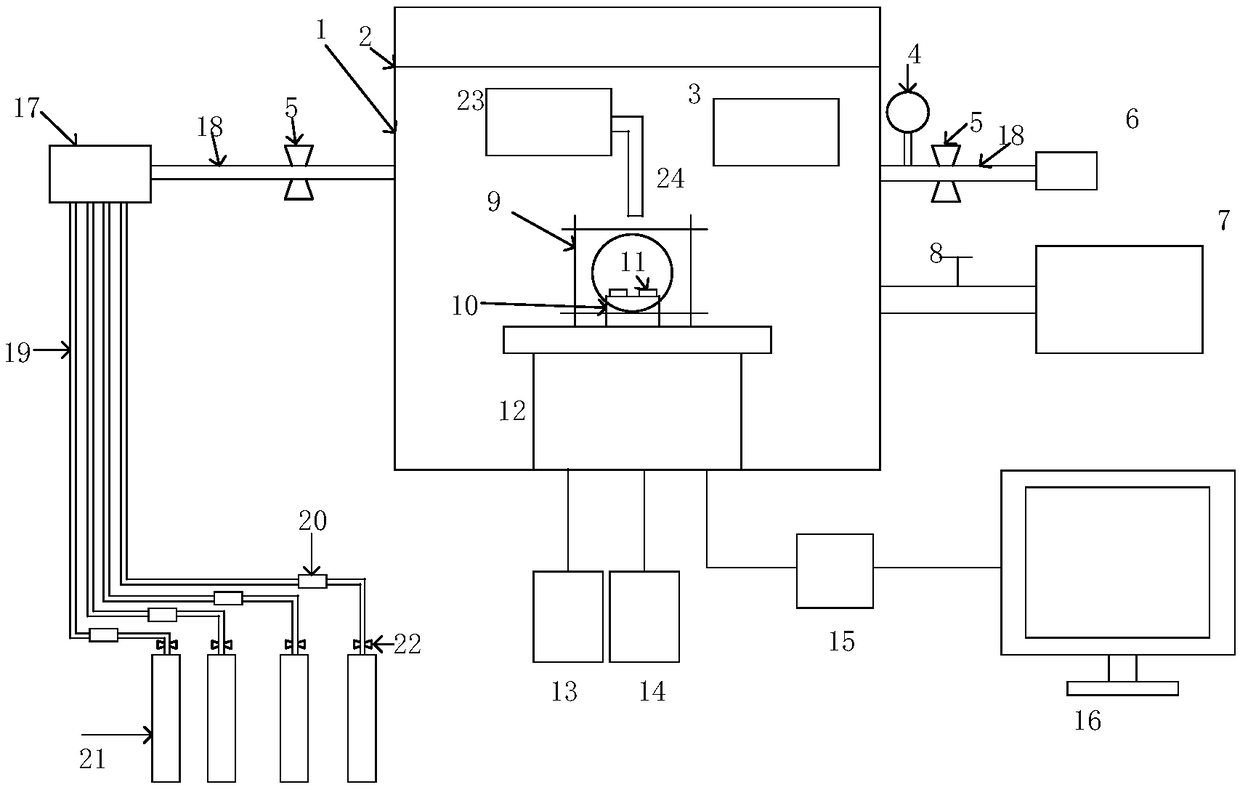
[0034] Install the gas sensor at the interface 11 where the gas sensor is placed. The output signal is led out to the outside data collector 15 through a wire, and the output end of the data collector 15 is connected to the signal input end of the computer 16. After the installation is completed, the test cavity is sealed by the sealing cover 2 to form a closed space. The test cavity is made of stainless steel, which can meet the pressure conditions during the experiment and the corrosiveness of the gas to be tested. Then, vacuuming is performed, and the specific operation is to close the shut-off valve 5 of the gas passage 18 of the intake part. Turn on the vacuum pump 6 to vacuumize the test chamber 1.

[0035] (2) Conduct experiments

[0036] According to the concentration requirements of the gas to be measured, the pressure reducing valve 22 and the shut-off valve 5 in the intake passage 19 are opened, and the voltage of...

Example Embodiment

[0039] Embodiment two:

[0040] The experiment preparation is the same as in Example 1. In the experiment part, humidity is used as the changing condition. By controlling the humidity controller 7, the humidity in the test chamber 1 is changed and the experimental data is recorded.

Example Embodiment

[0041] Example three

[0042] The experiment preparation is the same as in Example 1. In the experiment part, light is used as the changing condition. By controlling the light source controller 23 to change the light intensity in the cavity, the experimental data is recorded.


PUM


Abstract

The invention provides a gas sensor gas-sensing characteristic test system for a multi-physical field coupling environment. The gas sensor characteristic test system for the multi-physical field coupling environment comprises a gas distribution system, a test chamber, a test environment control unit and a test unit, wherein the gas distribution system can match test gas according to the required concentration and mix thoroughly and then the test gas can be introduced into the test chamber. The test chamber is a closed cylindrical box, and the bottom of the closed cylindrical box is connected with an external control unit through wires. The test environment control unit comprises an electromagnetic field control unit, a temperature control unit, a humidity control unit, and a vacuum pump. The test unit is used for performing real-time current collection of a gas sensor, and connected with an external computer to analyze obtained current data so as to obtain a dynamic characteristic testcurve of the sensor. The gas sensor characteristic test system for the multi-physical field coupling environment disclosed by the invention solves the technical problem that the existing gas sensor performance test device cannot simulate space magnetic field environments, and further satisfies the controllable temperature, humidity, pressure and illumination condition control to provide corresponding environments for testing performances of the gas sensor under different environmental conditions.

Description

technical field [0001] The invention belongs to the field of gas sensor testing and relates to a gas sensor characteristic testing system in a multi-physics field coupling environment. Background technique [0002] Gas-sensitive material refers to the material whose chemical and physical properties will change with the contact with the outside gas under certain conditions, and can convert its induction state into an electrical signal, and feedback the gas concentration in contact with the change of the electrical signal . At the same time, its chemical and physical conditions will change with the external temperature, humidity, magnetic field, light excitation and other conditions. Generally, in the current gas sensor test, the main environmental condition control includes: temperature, humidity, pressure, and light. [0003] Chinese patent CN105866331A discloses a gas sensor testing system for both dynamic and static gas distribution; Chinese patent CN101140252B discloses...

Claims


Application Information

Patent Timeline
IPC IPC(8): G01N27/04
CPCG01N27/04
Inventor 周渠卢昭睿王婷婷张福增廖一帆王国利彭姝迪唐超徐苓娜
Owner SOUTHWEST UNIVERSITY
Why Eureka
Try Eureka