
A kind of ion implantation method of silicon carbide device

A technology of ion implantation and ion implantation energy, which is applied in the field of ion implantation of silicon carbide devices, can solve the problems of high ion implantation damage and low activation rate of implanted ions, and achieve the effect of increasing activation rate and reducing ion implantation damage

Active Publication Date: 2021-01-15
北京国联万众半导体科技有限公司
View PDF7 Cites 0 Cited by
  • Summary
  • Abstract
  • Description
  • Claims
  • Application Information

AI Technical Summary

Problems solved by technology

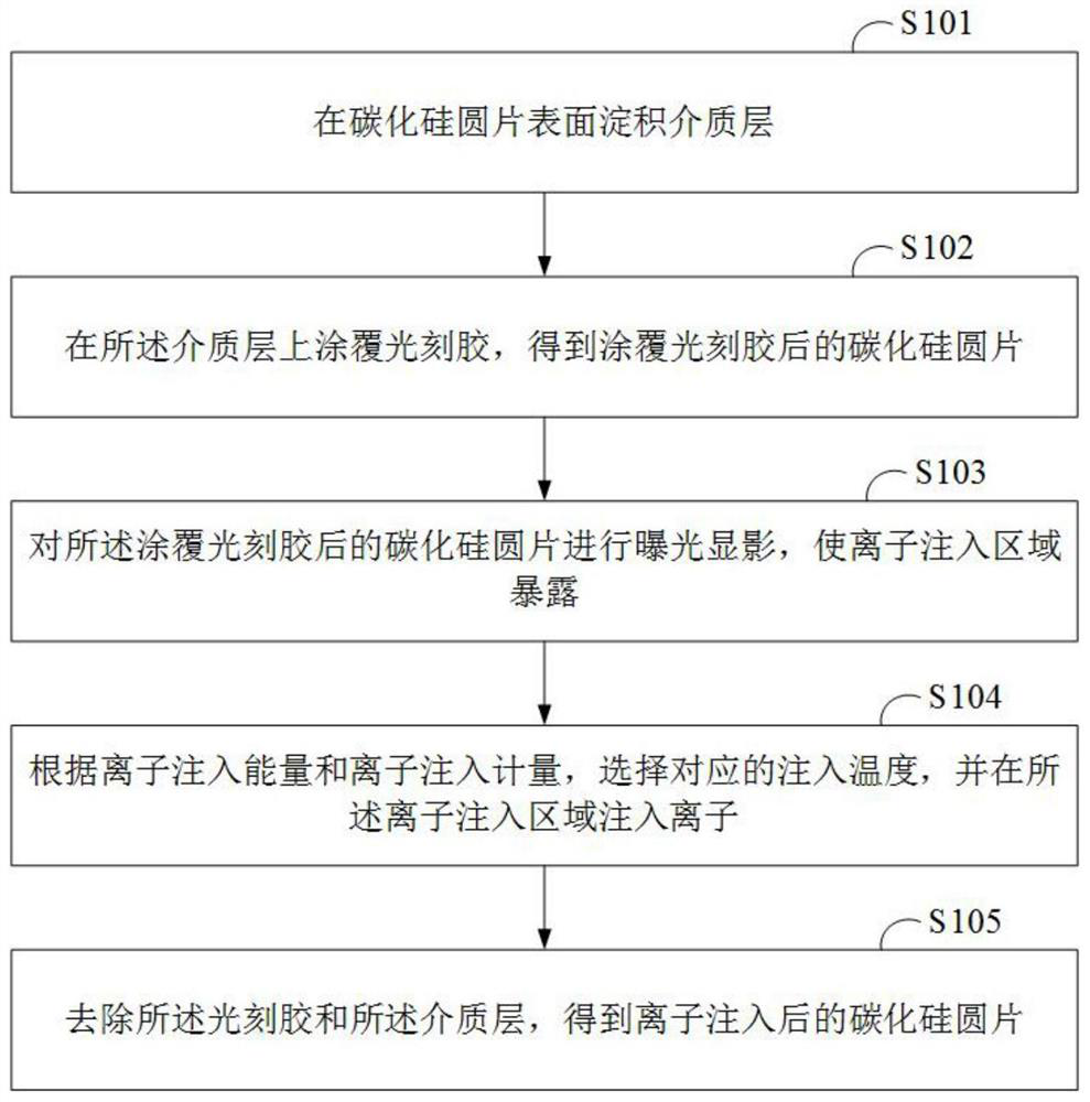
[0004] An embodiment of the present invention provides an ion implantation method for silicon carbide devices, aiming to solve the problems of high ion implantation damage and low activation rate of implanted ions in the prior art

Method used


Image

  • A kind of ion implantation method of silicon carbide device
  • A kind of ion implantation method of silicon carbide device
  • A kind of ion implantation method of silicon carbide device

Examples


Embodiment Construction

[0035] In order to enable those skilled in the art to better understand this solution, the technical solution in this solution embodiment will be clearly described below in conjunction with the accompanying drawings in this solution embodiment. Obviously, the described embodiment is a part of this solution Examples, but not all examples. Based on the embodiments in this solution, all other embodiments obtained by persons of ordinary skill in the art without creative efforts shall fall within the protection scope of this solution.

[0036] The term "comprising" and any other variants in the description and claims of this solution and the above drawings mean "including but not limited to", and are intended to cover non-exclusive inclusion.

[0037] The realization of the present invention is described in detail below in conjunction with specific accompanying drawing:

[0038] figure 1 An ion implantation method for a silicon carbide device provided by an embodiment of the pres...


PUM

PropertyMeasurementUnit
thicknessaaaaaaaaaa
thicknessaaaaaaaaaa
thicknessaaaaaaaaaa

Abstract

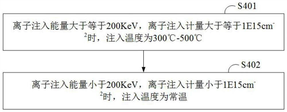
The invention discloses an ion injection method for a silicon carbide device. The method comprises the following steps that: depositing a dielectric layer on the surface of a silicon carbide wafer; coating the dielectric layer with photoresist to obtain the silicon carbide wafer coated with the photoresist; carrying out photoetching on the silicon carbide wafer coated with the photoresist to expose an ion injection area; according to ion injection energy and an ion injection dosage, selecting a corresponding injection temperature, and injecting ions into the ion injection area; and removing the photoresist and the dielectric layer to obtain the silicon carbide wafer subjected to ion injection. By use of the ion injection method, according to different ion injection energy and different ioninjection dosages, different injection temperatures are selected, an even injection structure is formed after multi-time injection, ion injection damage is reduced, and the activation rate of injection impurities is improved.

Description

technical field [0001] The invention relates to the technical field of semiconductor manufacturing, in particular to an ion implantation method for a silicon carbide device. Background technique [0002] Wide band gap semiconductor silicon carbide (SiC) has the advantages of large band gap, high breakdown field strength, and outstanding thermal conductivity, and has great potential in the field of power electronic device manufacturing. The ohmic contact of SiC devices requires heavy doping implantation, and the P-well implantation in VDMOS has a decisive impact on key parameters such as device threshold voltage and channel mobility. Reducing ion implantation damage and improving the activation rate of implanted ions has become an important part of SiC device manufacturing. key factor. [0003] At present, in the manufacturing process of SiC devices, the damage of ion implantation is high, and the activation rate of implanted ions is low. Contents of the invention [0004...

Claims


Application Information

Patent Timeline
Patent Type & Authority Patents(China)
IPC IPC(8): H01L21/265H01L21/266
CPCH01L21/26506H01L21/266
Inventor 秦龙宋洁晶胡泽先高渊高昶孙虎赵红刚吕鑫朱延超高三磊王强栋吕树海刘相伍
Owner 北京国联万众半导体科技有限公司
Learn More