Plasma treatment device

A plasma and processing device technology, applied in the field of ion plasma processing devices, can solve the problems of long current path, achieve the effect of ensuring symmetry, suppressing partial discharge, and shortening the return current path

Active Publication Date: 2020-12-29
ULVAC INC
View PDF8 Cites 0 Cited by
  • Summary
  • Abstract
  • Description
  • Claims
  • Application Information

AI Technical Summary

Problems solved by technology

Therefore, the return current path through the side wall portion in which the opening is formed is longer than the return current path through the other side wall portions, which causes unnecessary electric field distribution and electric field gradient.

Method used


Image

  • Plasma treatment device
  • Plasma treatment device
  • Plasma treatment device

Examples


Embodiment Construction

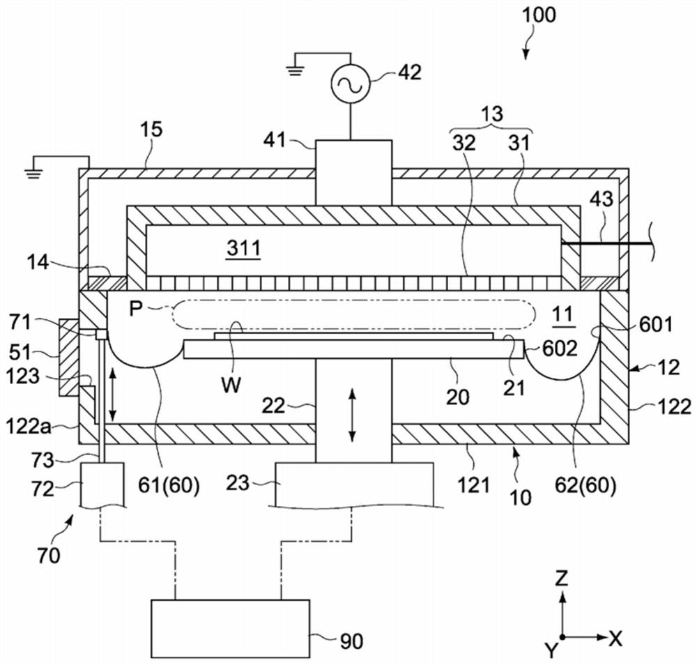
[0068]Hereinafter, embodiments of the present invention will be described with reference to the drawings. In this embodiment, a plasma CVD (Chemical Vapor Deposition) apparatus is taken as an example, and the plasma processing apparatus will be described.

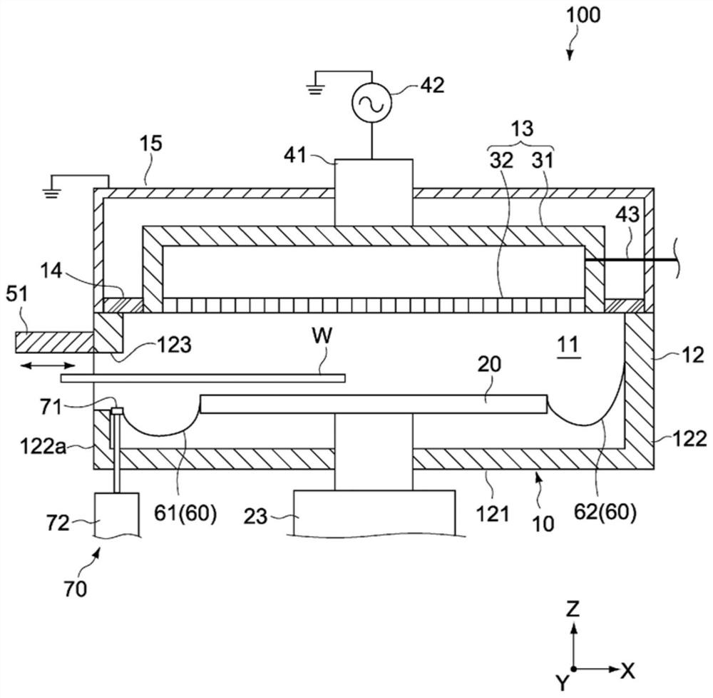
[0069]figure 1 as well asfigure 2 Is a schematic side cross-sectional view showing the structure of the plasma CVD apparatus according to this embodiment,figure 1 ,figure 2 The conditions at the time of film formation and the conditions at the time of carrying out the substrate are shown respectively.

[0070]In addition, in each drawing, the X axis, the Y axis, and the Z axis indicate three axis directions that cross each other perpendicularly, the X axis and the Y axis correspond to the horizontal direction, and the Z axis corresponds to the height direction.


PUM


Abstract

Provided is a plasma processing apparatus capable of shortening a return current path and ensuring symmetry. A plasma processing apparatus according to an embodiment of the present invention includes a chamber main body, a stage, a high-frequency electrode, a plurality of ground members, and a movable unit. The chamber main body has a side wall, and a part of the side wall includes an opening through which the substrate can pass. The plurality of ground members are disposed around the stage, and are electrically connected between the side wall and the stage. The movable unit has a support that supports a first ground member that is a part of the plurality of ground members. The movable unit is configured such that the supporting body and the first grounding member can be electrically connected to the inner peripheral surface at a first position where the first grounding member faces the inner peripheral surface of the opening with the first grounding member interposed therebetween. to move between the second positions.

Description

Technical field[0001]The present invention relates to a plasma processing apparatus such as a plasma CVD apparatus.Background technique[0002]Generally, a plasma CVD apparatus generates plasma of a film-forming gas in the film-forming space (reaction chamber) between the high-frequency electrode (cathode) and the stage (anode), and deposits the reaction product on the stage On the substrate. A plurality of grounding components electrically connected to the vacuum chamber are arranged around the stage. These grounding components form a return current path for returning high-frequency current from the stage to the power source via the vacuum chamber.[0003]Here, if the return current path is not optimized, undesired discharge may occur in places other than between the cathode and anode. For example, when the return current path is anisotropically dense and uneven, the return current is concentrated in the dense path, and electric field distribution and electric field gradient are genera...

Claims


Application Information

Patent Timeline
Patent Type & Authority Patents(China)
IPC IPC(8): C23C16/505H01L21/3065H01L21/31H05H1/46
CPCC23C16/505H01L21/3065H01L21/31H05H1/46C23C16/4583H01J37/32513H01J37/32623
Inventor 中村文生田丸义久矢岛贵浩加藤裕子神保洋介植喜信冈野秀一冈山智彦
Owner ULVAC INC
Why Eureka
Try Eureka