
Double wrap spring, rotation device and system to be actuated

A rotary device, dual technology, applied in the field of dual wrap springs, can solve the problem of late entry into expectations, etc.

Active Publication Date: 2019-03-15
SCHAEFFLER TECH AG & CO KG
View PDF7 Cites 0 Cited by
  • Summary
  • Abstract
  • Description
  • Claims
  • Application Information

AI Technical Summary

Problems solved by technology

[0011] A hitherto known disadvantage of double wrap springs is that they are either realized by means of additional components and / or respond relatively elastically to The torque or the direction of rotation reacts in reverse, so that the desired braking or locking effect to be achieved by the double wrap spring is relatively late.

Method used


Image

  • Double wrap spring, rotation device and system to be actuated
  • Double wrap spring, rotation device and system to be actuated
  • Double wrap spring, rotation device and system to be actuated

Examples


Embodiment Construction

[0054] To illustrate the conventional double wrap spring has been referred to Figures 1 to 5 .

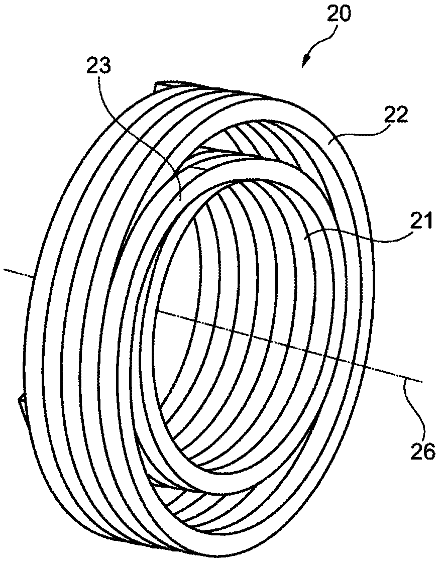
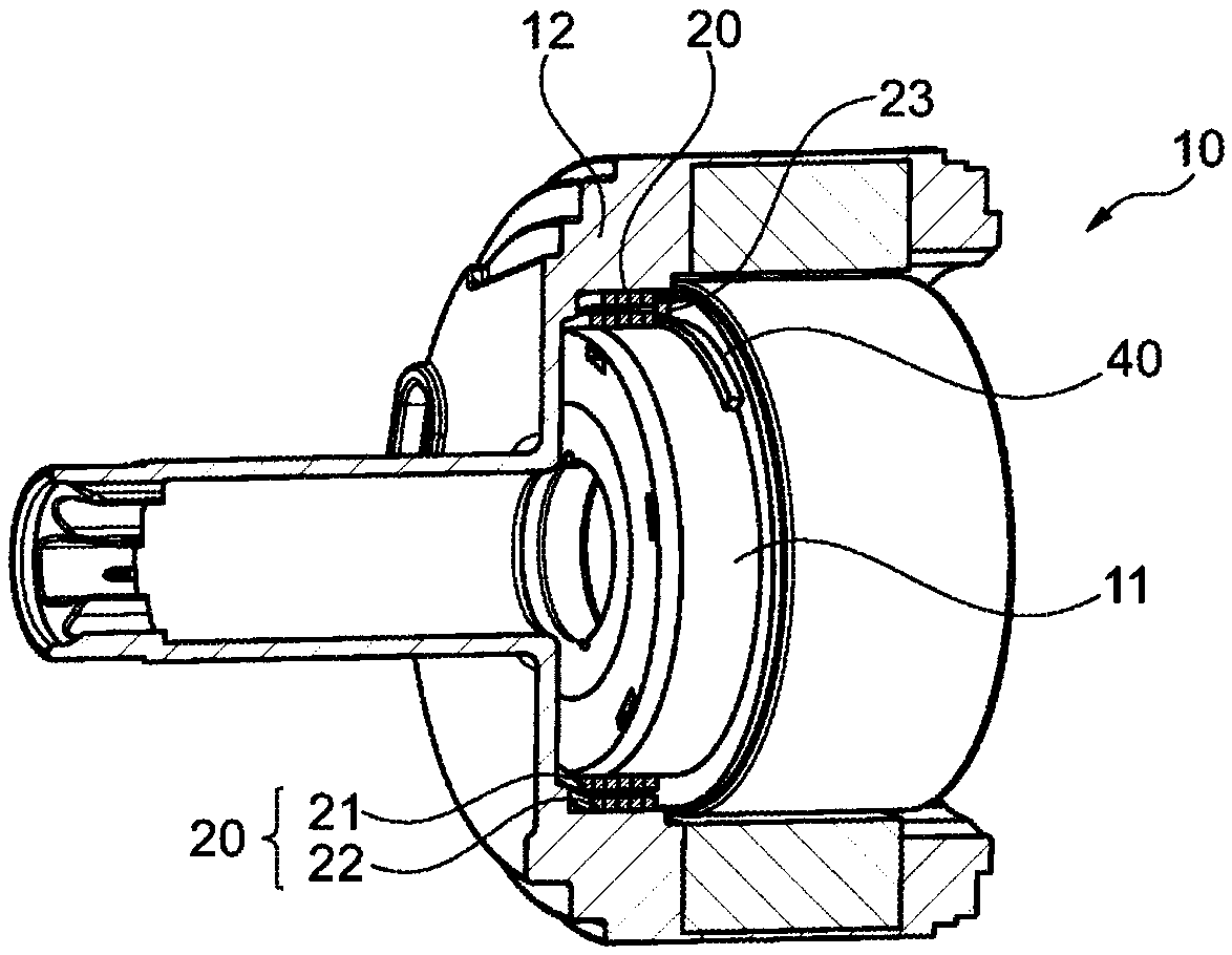
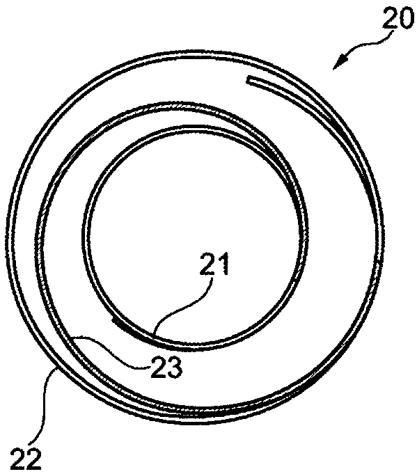
[0055] exist Figures 6 to 9 It can be seen in the uninstalled state ( Image 6 with 8 ) and installed state ( Figure 7 with 9 ) according to two different designs of the double wrap spring of the present invention. as in Image 6 As shown in , the double wrap spring of the embodiment shown here has an inner wrapping region 21 and an outer wrapping region 22 which, due to the eccentricity of the wrapping regions 21, 22, are in the same direction as the wrapping region In the region of the transition between 21 , 22 there is an extremely small distance a from one another. The transition region 23 between the inner wrapping region 21 and the outer wrapping region 22 is designed here to be extremely short and has a correspondingly small radius of curvature Rk. Figure 7 This embodiment of the double wrap spring is shown in the installed state, in which it can be seen that th...


PUM


Abstract

The invention relates to a double wrap spring and to a rotation device with the double wrap spring according to the invention, and to a system to be actuated. The double wrap spring (20) comprises aninner winding region (21) and an outer winding region (22), and also a transition region (23) mechanically connecting the inner winding region (21) to the outer winding region (22). In the non-installed state of the double wrap spring, the winding regions (21, 22) are arranged eccentrically with respect to each other. With the double wrap spring proposed here, elastic deformation of a transition region between the inner winding region and the outer winding region can be greatly restricted, and therefore energy input into the double wrap spring, the energy being input in the form of a torsionalmoment, is not absorbed by the transition region, but rather is substantially completely and immediately used for braking or blocking the components making contact with the double wrap spring.

Description

technical field [0001] The invention relates to a double wrap spring having an inner wrapping region and an outer wrapping region arranged radially outward relative thereto. Furthermore, the invention relates to a rotary device with a double wrap spring according to the invention, and a system to be actuated, in particular a clutch device, which comprises a rotary device according to the invention. Background technique [0002] In order to operate the clutch it is often necessary to traverse a translation path in order to disengage the clutch halves from each other or to engage them with each other. For this purpose, actuating devices are required, which are also referred to as actuators and by means of which the required forces can be generated on the corresponding paths. For this purpose there are actuators which convert a rotational movement of one component into an axial movement of the other component, for example in order to open or close a clutch. Typical actuators ...

Claims


Application Information

Patent Timeline
IPC IPC(8): F16D13/08F16D41/04F16D41/20F16D41/02F16H25/22
CPCF16D13/08F16D41/02F16D41/04F16D41/203F16D41/206F16H25/2252F16H2025/2463
Inventor 拉尔斯·舒曼拉兹洛·曼
Owner SCHAEFFLER TECH AG & CO KG
Learn More