Machining system of unstructured component

An unstructured, processing system technology, applied in metal processing equipment, manufacturing tools, welding equipment, etc., can solve the problems of waste material cost, low processing accuracy, low production efficiency, etc., to improve processing accuracy and product consistency , Save the time of repeated selection and improve work efficiency

Inactive Publication Date: 2019-03-19
宁波欧尼克科技有限公司
View PDF6 Cites 7 Cited by
  • Summary
  • Abstract
  • Description
  • Claims
  • Application Information

AI Technical Summary

Problems solved by technology

Compared with traditional manual labor, automatic processing machine tools are flexible and convenient to operate, high in production efficiency, and meet the needs of modern production. Traditional cutting, punching, milling and other processes are carried out separately, and the processed products will be processed during the handling process. It will be damaged, the machining accuracy is not high, the consistency is poor, and the scrap rate is high, which not only wastes material costs, but also reduces production efficiency, especially some products are assembled from many unstructured parts, and these unstructured The processing procedures of specialized parts are easy to be damaged, and in the current production, sometimes it is necessary to make different optional packages according to the different requirements of customers. The production department needs to quickly arrange the corresponding optional packages according to the production plan to meet the production needs. It needs to use The Internet of Things technology passes a large number of unstructured parts through the automated production line. Before final assembly, all unstructured parts need to be automatically identified and matched according to the set. This requires the production planning department to formulate optional packages according to the order in time and ensure that Large quantities of unstructured parts are produced quickly and sent to the assembly department for assembly in time to ensure normal production and facilitate the marketing department to place orders

Method used


Image

  • Machining system of unstructured component

Examples


Embodiment Construction

[0027] The following will clearly and completely describe the technical solutions in the embodiments of the present invention with reference to the accompanying drawings in the embodiments of the present invention. Obviously, the described embodiments are only some, not all, embodiments of the present invention. Based on the embodiments of the present invention, all other embodiments obtained by persons of ordinary skill in the art without creative efforts fall within the protection scope of the present invention.

[0028] It should be noted that, in the case of no conflict, the embodiments of the present invention and the features in the embodiments can be combined with each other.

[0029] The present invention will be further described below in conjunction with the accompanying drawings and specific embodiments, but not as a limitation of the present invention.

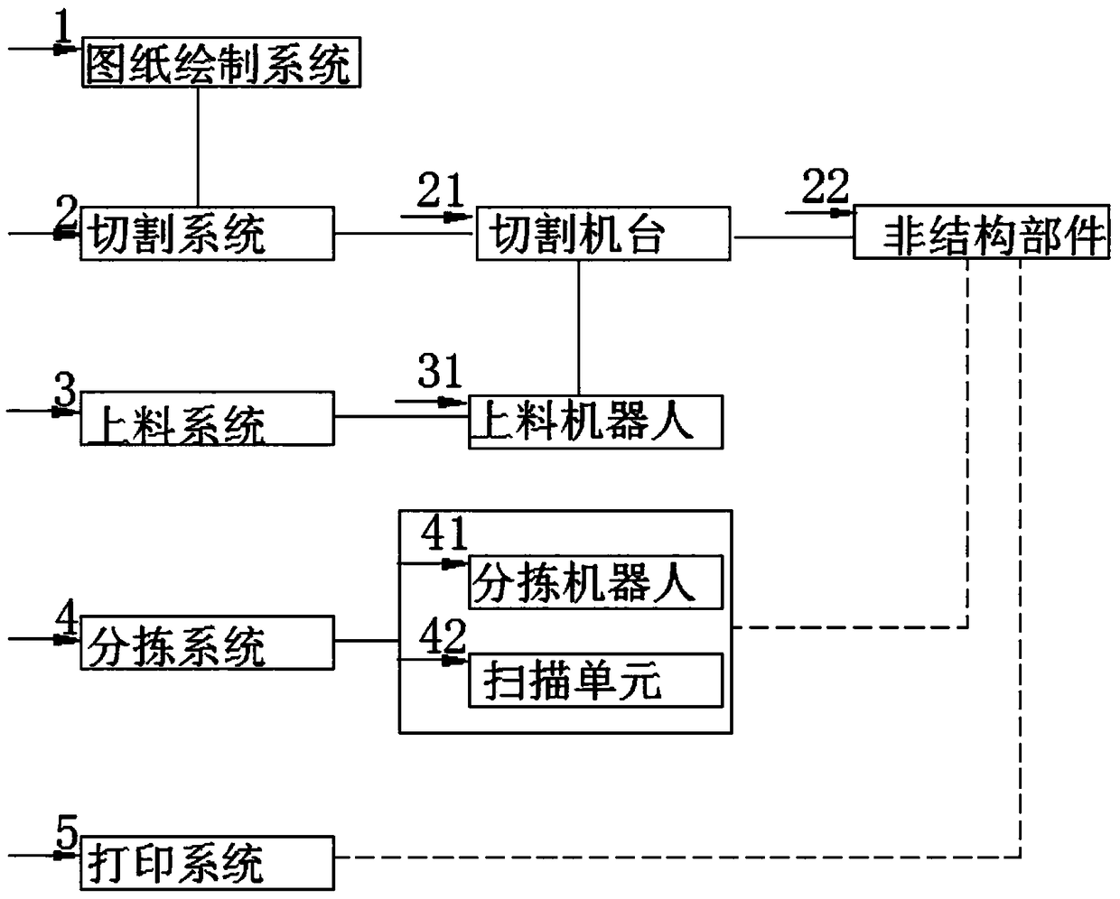
[0030] Such as figure 1 As shown, in a preferred embodiment of the present invention, according to the problems...


PUM


Abstract

The invention discloses a machining system of an unstructured component. The machining system comprises a drawing system and a cutting system. The cutting system is used for determining cutting schemes of each unstructured component based on production drawings and component tables. A cutting machine table is used for cutting a plate into unstructured components based on the cutting schemes. A feeding system is used for conveying the plate onto the cutting machine table. A sorting system is used for determining orders of each unstructured component by identifying a unique identity, and sortingthe unstructured components out based on identifying results. A sorting robot adopts mechanical arms to sort each unstructured component out. The rejection rate can be reduced, waste is reduced, corresponding optional packages can be set up for customers to choose based on customer requirements, order making and using of the market department are facilitated, the time of repeated selection is greatly shortened, and working efficiency is improved.

Description

technical field [0001] The invention relates to the technical field of mechanical automation control, in particular to a processing system for unstructured parts. Background technique [0002] With the continuous development of industry, the mechanical processing industry is developing more and more rapidly in our country, and the requirements for various industrial technologies are also higher, especially for precision machining products. In order to replace traditional manual labor methods, save labor and reduce Labor-intensive, automated processing equipment is widely used. Compared with traditional manual labor, automatic processing machine tools are flexible and convenient to operate, high in production efficiency, and meet the needs of modern production. Traditional cutting, punching, milling and other processes are carried out separately, and the processed products will be processed during the handling process. It will be damaged, the machining accuracy is not high, ...

Claims


Application Information

Patent Timeline
Patent Type & Authority Applications(China)
IPC IPC(8): B23K26/38B23K26/70B07C5/00
CPCB07C5/00B23K26/38B23K26/70
Inventor 吴军晖翁良杰李荔陈江群贺鹏程
Owner 宁波欧尼克科技有限公司
Why Eureka
Try Eureka