A deburring device for excessive brackets of automobile batteries

A storage battery and deburring technology, which is applied to machine tools suitable for grinding workpiece edges, grinding workpiece supports, grinding/polishing safety devices, etc., which can solve problems such as reduced work efficiency, easy injury to hands, and poor brush safety , to achieve the effect of improving work efficiency

Active Publication Date: 2020-09-08
合肥东铭机械制造有限公司
View PDF2 Cites 0 Cited by
  • Summary
  • Abstract
  • Description
  • Claims
  • Application Information

AI Technical Summary

Problems solved by technology

[0002] During the processing of automotive battery transition brackets, burrs are often produced on the surface of the parts. These burrs not only affect the appearance of the parts, but more importantly, directly reduce the quality of the parts and affect the performance of the product. Therefore, it is necessary to deburr the parts; currently in Many small and medium-sized enterprises or family workshops often use manual methods to remove burrs or use angle grinders to remove burrs, but the brushes used have poor safety and are easy to hurt hands. It is also easy to produce a large amount of metal debris, and if the metal debris is not handled in time, the working environment will deteriorate. At the same time, the splash of metal debris can easily hurt workers. Figure 5 ) When the car battery transition bracket is polished with a brush or an angle grinder, the burrs will transition from the upper surface to the horizontal surface, and vice versa. It will take many times to remove the burrs of the battery transition bracket and reduce the work. efficiency, impact on output

Method used


Image

  • A deburring device for excessive brackets of automobile batteries
  • A deburring device for excessive brackets of automobile batteries
  • A deburring device for excessive brackets of automobile batteries

Examples


Embodiment Construction

[0020] Embodiments of the present invention are described in detail below, examples of which are shown in the drawings, wherein the same or similar reference numerals designate the same or similar elements or elements having the same or similar functions throughout. The embodiments described below by referring to the figures are exemplary and are intended to explain the present invention and should not be construed as limiting the present invention. In the description of the present invention, it should be understood that the orientation or positional relationship indicated by the terms "upper", "lower", "front", "rear" etc. is based on the orientation or positional relationship shown in the drawings, and is only for It is convenient to describe the present invention and simplify the description, but does not indicate or imply that the device or element referred to must have a specific orientation, be constructed and operate in a specific orientation, and thus should not be con...


PUM


Abstract

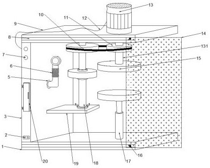
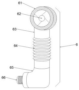
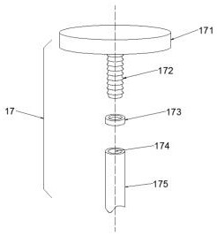
The invention discloses a deburring device used for automobile storage battery transition supports. The deburring device comprises a bottom plate, a vertical plate welded to the bottom plate, and a transverse plate welded to the top end of the vertical plate; the front faces of the bottom plate and the transverse plate are slidably connected with a transparent plate, and a bracket assembly is arranged on the upper surface of the bottom plate; a dust remover is arranged above a supporting plate, and a sander is arranged on the supporting plate; and a grinding disc is fixed to one end of a connecting shaft of a motor. The device is provided with the sander to cooperate with the grinding disc so that burrs of the automobile supports placed on the bracket assembly can be polished away; by mounting an abrasion wheel with the length being greater than the diameter on the sander and meanwhile cooperating with vertical adjusting of the bracket assembly, the automobile supports with different thicknesses can be polished by the device; and metal debris can be prevented from being splashed into human eyes through the arranged transparent plate, the metal debris can be sucked out in time through the arranged dust remover, and thus influences of metal debris dust on workers during polishing of the automobile supports are lowered.

Description

technical field [0001] The invention relates to a mechanical processing equipment, in particular to a deburring device for the excessive bracket of the automobile storage battery. Background technique [0002] During the processing of automotive battery transition brackets, burrs are often produced on the surface of the parts. These burrs not only affect the appearance of the parts, but more importantly, directly reduce the quality of the parts and affect the performance of the product. Therefore, it is necessary to deburr the parts; currently in Many small and medium-sized enterprises or family workshops often use manual methods to remove burrs or use angle grinders to remove burrs, but the brushes used have poor safety and are easy to hurt hands. It is also easy to produce a large amount of metal debris, and if the metal debris is not handled in time, the working environment will deteriorate. At the same time, the splash of metal debris can easily hurt workers. Figure 5 )...

Claims


Application Information

Patent Timeline
Patent Type & Authority Patents(China)
IPC IPC(8): B24B9/04B24B55/04B24B55/06B24B41/06
CPCB24B9/04B24B41/06B24B55/04B24B55/06
Inventor 张永寿
Owner 合肥东铭机械制造有限公司
Why Eureka
Try Eureka