Exhaust gas combustion furnace and exhaust gas treatment equipment

A kind of waste gas treatment equipment, waste gas combustion technology

Inactive Publication Date: 2019-03-19
SHANGHAI BAOSTEEL ENERGY TECH
View PDF5 Cites 1 Cited by
  • Summary
  • Abstract
  • Description
  • Claims
  • Application Information

AI Technical Summary

Problems solved by technology

[0004] The existing regenerative combustion device preheats the industrial waste gas first, which can improve the treatment effect of industrial waste gas under certain circumstances, but the gas and industrial waste gas in the existing regenerative combustion device cannot be fully combusted, which on the one hand reduces the The utilization rate of gas, on the other hand, also slows down the decomposition of harmful gases in industrial waste gas

Method used


Image

  • Exhaust gas combustion furnace and exhaust gas treatment equipment

Examples


Embodiment 1

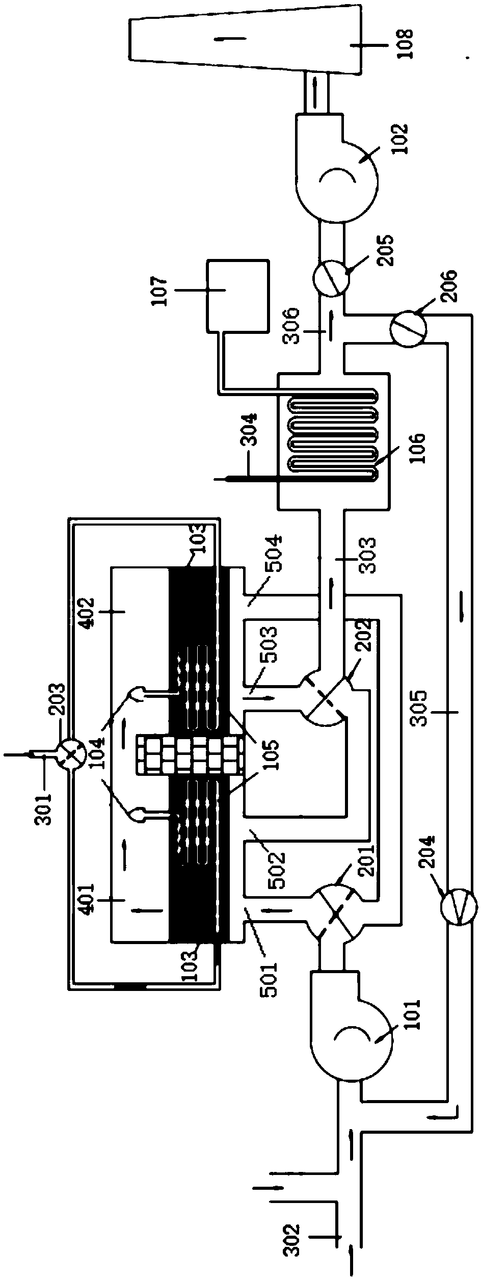
[0043] like figure 1 As shown, a waste gas combustion furnace proposed by the present invention includes a combustion chamber for burning and decomposing industrial waste gas. The combustion chamber includes a first combustion chamber 401 and a second combustion chamber 402. The upper part of the first combustion chamber 401 and the second combustion chamber The upper part of the combustion chamber 402 is connected; the heat storage body 103 is used to store heat, and the bottom of the first combustion chamber 401 and the bottom of the second combustion chamber 402 are equipped with a heat storage body 103; the gas preheating pipeline 105, the gas The air inlet of the preheating pipeline 105 is used to communicate with the external gas delivery pipeline 301, and each regenerator 103 is provided with a gas preheating pipeline 105, and the gas outlet of the gas preheating pipeline 105 extends out to burn chamber; and a burner 104, the gas outlet of each gas preheating pipeline 1...

Embodiment 2

[0049] like figure 1 As shown, the present invention proposes an exhaust gas treatment equipment, including the above-mentioned exhaust gas combustion furnace; the exhaust gas delivery pipeline 302 communicates with the first air inlet 501 and the second air inlet 504, and circulates alternately to the first combustion chamber 401, The second combustion chamber 402 transports industrial waste gas; the exhaust pipeline 303 communicates with the first exhaust port 502 and the second exhaust port 503, and circulates and alternately discharges the gas after the industrial waste gas combustion in the first combustion chamber 401, the second The gas after the combustion of industrial waste gas in the combustion chamber 402; the gas delivery pipeline 301 communicates with the gas preheating pipeline 105 in the first combustion chamber 401 and the gas preheating pipeline 105 in the second combustion chamber 402, and the cycle alternates Gas is delivered to the first combustion chamber...


PUM


Abstract

The invention discloses an exhaust gas combustion furnace and exhaust gas treatment equipment. The exhaust gas combustion furnace comprises a combustion chamber, heat accumulators, gas preheating pipelines, combustors, an exhaust gas conveying pipeline, an exhaust pipeline and a gas conveying pipeline, wherein the combustion chamber comprises a first combustion chamber and a second combustion chamber; the upper part of the first combustion chamber communicates with the upper part of the second combustion chamber; each heat accumulator is positioned at the bottom of the combustion chamber; a gas inlet of each gas preheating pipeline is used for communicating with the external gas conveying pipeline; each heat accumulator is internally provided with the corresponding gas preheating pipeline;a gas outlet of each gas preheating pipeline extends out of the combustion chamber; and the air outlet of each gas preheating pipeline is provided with the corresponding combustor. By the scheme, onone hand, the exhaust gas combustion furnace increases the utilization rate of gas, on the other hand, the exhaust gas combustion furnace quickens decomposition of harmful gases in the exhaust gas, reduces consumption of the gas, improves the incineration efficiency and effect of the exhaust gas and achieves good economical benefits and environmental protection benefits.

Description

technical field [0001] The invention belongs to the field of waste gas combustion, and in particular relates to a waste gas combustion furnace and waste gas treatment equipment. Background technique [0002] VOCs (Volatile Organic Compounds) are volatile organic compounds. There are many methods to deal with volatile organic compounds. Among them, catalytic combustion (catalytic oxidizers) is an effective method for treating waste gas containing organic solvents. [0003] The device for treating organic waste gas has a regenerative catalytic combustion device, which has high utilization efficiency of catalytic combustion waste heat. It is an internationally recognized energy-saving organic waste gas treatment device, but because the catalyst used is generally a noble metal catalyst, the cost of the catalyst is relatively high. , and the current life of noble metal catalysts is not long enough, therefore, the recycling of catalysts has also become an important factor limiting...

Claims


Application Information

Patent Timeline
Patent Type & Authority Applications(China)
IPC IPC(8): F23G7/06
CPCF23G7/068F23G2206/203Y02E20/12
Inventor 崔鹏沈磊
Owner SHANGHAI BAOSTEEL ENERGY TECH
Why Eureka
Try Eureka