Liquid metal pulse heat pipe

A liquid metal and pulse heat pipe technology, applied in the field of heat pipes, can solve the problems of large calorific value, low heat transfer limit of heat pipes, and low heat transfer efficiency of heat pipes, and achieve the effect of wide working temperature range and high efficiency

Inactive Publication Date: 2019-03-19
YUNAN JINGCHUANG LIQUID METAL THERMAL CONTROL TECH RES & DEV CO LTD
View PDF5 Cites 1 Cited by
  • Summary
  • Abstract
  • Description
  • Claims
  • Application Information

AI Technical Summary

Problems solved by technology

[0006] The purpose of the present invention is to provide a liquid metal pulse heat pipe to solve the problem that the heat pipe in the prior art only transmits the heat exchange working medium from the near end to the far end of the heat pipe through the liquid-absorbing

Method used


Image

  • Liquid metal pulse heat pipe
  • Liquid metal pulse heat pipe
  • Liquid metal pulse heat pipe

Examples


Embodiment 1

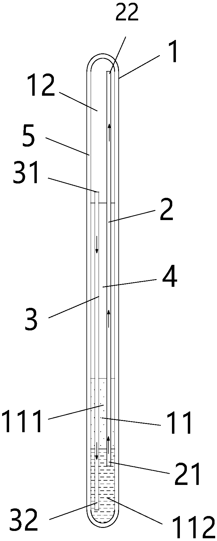
[0032] Such as figure 1 As shown, the figure schematically shows that the liquid metal pulse heat pipe includes a pipe body 1 , an ascending pipe 2 and a return pipe 3 .

[0033] In the embodiment of the present application, a heating chamber 11 and a heat dissipation chamber 12 which are independent of each other are sequentially constructed inside the pipe body 1 from bottom to top. Boiling point working medium 111 and liquid metal 112.

[0034] The ascending pipe 2 is arranged inside the pipe body 1 and runs through the heating chamber 11 and the heat dissipation chamber 12 .

[0035] The return pipe 3 is arranged inside the pipe body 1 and runs through the heating chamber 11 and the heat dissipation chamber 12, wherein the return pipe 3 and the ascending pipe 2 are spaced apart, and the heating chamber 11 is heating, so that the low-boiling point working fluid 111 is heated and evaporated into a gaseous working medium, and the liquid metal 112 and the gaseous working med...


PUM


Abstract

The invention relates to the technical field of heat pipes, and discloses a liquid metal pulse heat pipe. The liquid metal pulse heat pipe comprises a pipe body, a rising pipeline and a returning pipeline; a heating chamber and a heat dissipation chamber which are independent mutually are sequentially constructed in the pipe body from bottom to top, and a low-boiling-point working medium and liquid metal are arranged in the heating chamber from top to bottom in a layered mode; the rising pipeline is arranged in the pipe body and penetrates through the heating chamber and the heat dissipation chamber; the returning pipeline is arranged in the pipe body and penetrates through the heating chamber and the heat dissipation chamber; and the returning pipeline and the rising pipeline are arrangedin a spaced mode. By heating the heating chamber, the low-boiling-point working medium is heated and evaporated into a gaseous work medium, and under the effect of the gas pressure, the liquid metaland the gaseous work medium are alternately conveyed from the heating chamber to the heat dissipation chamber along the rising pipeline in a segmented mode, and then conveyed from the heat dissipationchamber back to the heating chamber along the return pipeline; and the liquid metal pulse heat pipe has the advantages of high heat transfer efficiency and large heat transfer limit.

Description

technical field [0001] The invention relates to the technical field of heat pipes, in particular to a liquid metal pulse heat pipe. Background technique [0002] The 21st century has entered the era of portability and miniaturization, but the integration of electronic processing chips is getting higher and higher, but the volume is getting smaller and smaller. The high frequency and high speed of electronic devices and the density and miniaturization of integrated circuits have caused a sharp increase in the heating power and power density of electronic devices. The cooling technology of electronic devices has become the key to the development of microelectronics technology, requiring features such as compactness, reliability, flexibility and high heat dissipation efficiency. [0003] A heat pipe is a heat transfer element that relies on the phase change of its internal working liquid to transfer heat. It can transfer a large amount of heat through a small cross-sectional a...

Claims


Application Information

Patent Timeline
IPC IPC(8): F28D15/02
CPCF28D15/025
Inventor 郑立聪关志祥谢开旺盛磊刘静
Owner YUNAN JINGCHUANG LIQUID METAL THERMAL CONTROL TECH RES & DEV CO LTD
Why Eureka
Try Eureka