Supercharge Your Innovation With Domain-Expert AI Agents!

Ultrasonic visual detection method and ultrasonic visual detector

A detection method, ultrasonic technology, applied in the direction of using acoustic measurement for testing, optical method for testing, testing dielectric strength, etc. problems, to achieve the effect of easy-to-understand detection efficiency, accurate detection data, and easy portability

Inactive Publication Date: 2019-03-19
RED PHASE INC
View PDF5 Cites 4 Cited by
  • Summary
  • Abstract
  • Description
  • Claims
  • Application Information

AI Technical Summary

Problems solved by technology

However, although traditional ultrasonic detection methods can detect and discover potential faults to a certain extent, they cannot further accurately determine the source and location of faults
For example, the Chinese invention patent with the application number 201410722389.0 provides a method for visualizing the audio data after processing the ultrasonic discharge detection signal. Although it can visually display whether partial discharge occurs at the position corresponding to the sensor with the ultrasonic data statistical map, but the The exact location of the above-mentioned "position corresponding to the sensor" (that is, the specific fault point, such as the position of a corner of an insulator) cannot be determined intuitively, and only the approximate range of the fault can be obtained, which is not conducive to accurate troubleshooting
Furthermore, because it cannot determine the fault point intuitively and quickly, it cannot meet the requirements of rapid inspection

Method used


Image

  • Ultrasonic visual detection method and ultrasonic visual detector
  • Ultrasonic visual detection method and ultrasonic visual detector
  • Ultrasonic visual detection method and ultrasonic visual detector

Examples


Embodiment 1

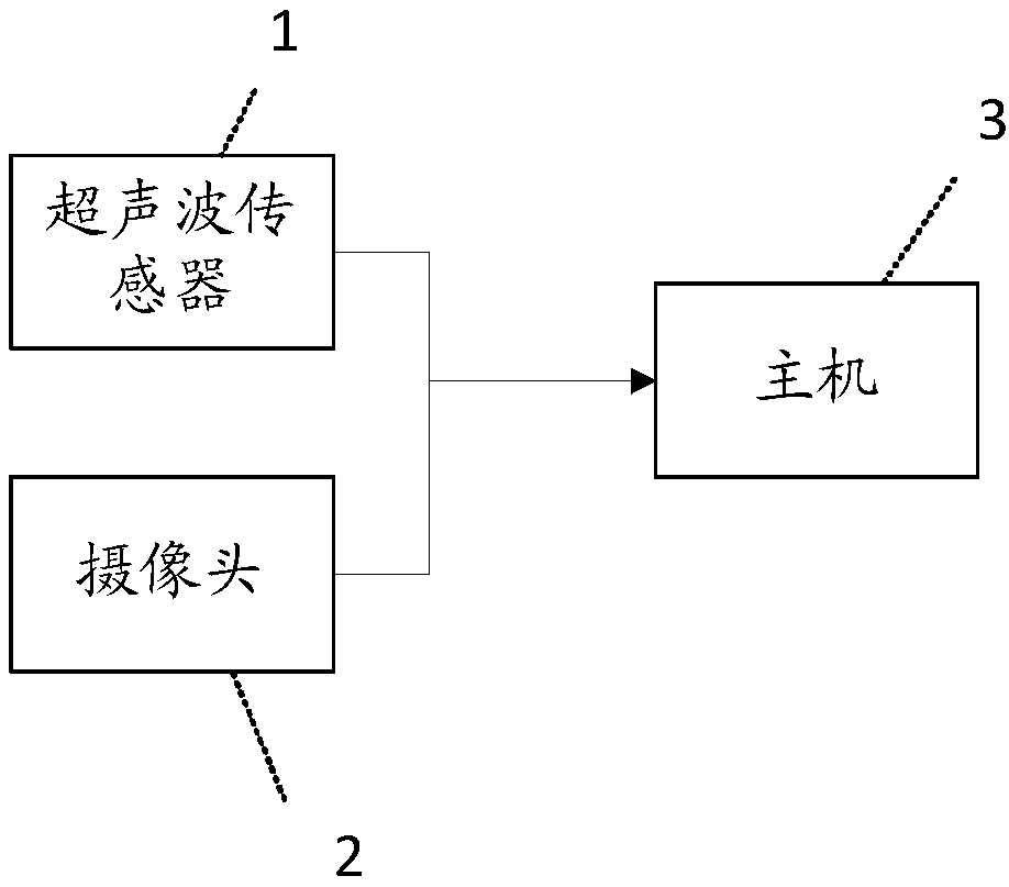
[0062] Please refer to figure 1 and figure 2 , this embodiment provides an ultrasonic visualization detector, such as figure 2 As shown, including the detector 01 and the host 02, the detector 01 and the host 02 are connected through a high-frequency signal transmission cable (namely, the shielded cable 03). As the signal transmission line between the two, it can effectively prevent external interference during signal transmission. and signal attenuation. Preferably, the structure is a multi-core shielded cable, such as a four-core shielded cable.

[0063] The detector 01 is equipped with an ultrasonic sensor 1 and a camera 2 . The detection angle of view of the ultrasonic sensor 1 corresponds to the imaging angle of view of the camera 2; that is, the signal detection point of the ultrasonic sensor is set at the same point as the imaging focus of the camera. Specifically, the ultrasonic signal propagates along a straight line within a certain distance, and the camera als...

Embodiment 2

[0073] This embodiment is further expanded on the basis of the first embodiment, and its functions are enriched. The similarities will not be repeated, the differences are:

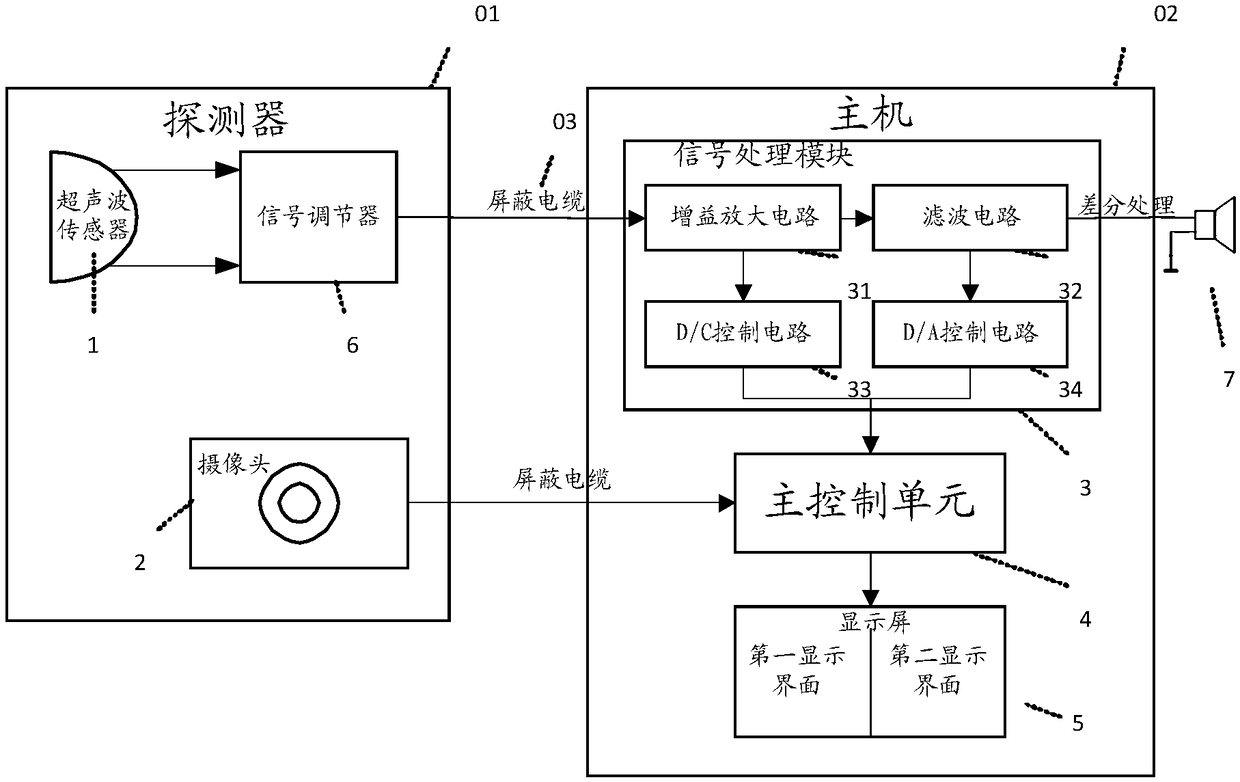
[0074] Such as image 3 As shown, the host 02 specifically includes a signal processing module 3, a main control unit 4 and a display screen 5; the display screen 5 is configured with a first display interface and a second display interface.

[0075] The ultrasonic sensor 1 , the shielded cable 03 , the signal processing module 3 , the main control unit 4 and the display screen are connected sequentially; the camera, shielded cable, main control unit and the display screen are connected sequentially.

[0076] The signal processing module 3 is configured to convert the ultrasonic signal collected by the ultrasonic sensor into an audio signal audible to the human ear through fast Fourier transform, and generate a corresponding audio waveform spectrogram according to the audio signal. In this way, the ultr...

Embodiment 3

[0102] This embodiment is an ultrasonic visualization detection method corresponding to the first embodiment above, including:

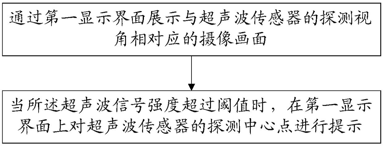
[0103] Displaying a camera picture corresponding to the detection angle of view of the ultrasonic sensor through the first display interface;

[0104] When the ultrasonic signal strength exceeds the threshold, the detection point of the ultrasonic sensor is prompted on the first display interface.

[0105] Specifically, the eye-catching degree of the prompt is directly proportional to the strength of the ultrasonic signal.

[0106] The prompt is to mark the water ripples with a preset number of circles; the greater the strength of the ultrasonic signal, the more circles of the marked water ripples.


PUM


Abstract

The invention provides an ultrasonic visual detection method and an ultrasonic visual detector, wherein the method comprises the following steps of: displaying a camera picture corresponding to a detection visual angle of an ultrasonic sensor through a first display interface; and prompting a detection point of the ultrasonic sensor on the first display interface when ultrasonic signal intensity exceeds a threshold value. The ultrasonic visual detection method and the ultrasonic visual detector are characterized in that the device is convenient to carry and simple to operate; detection data isaccurate and visualized, a whole detection process is short in time consumption, high in efficiency, safe and reliable, and the like, thereby providing a new effective detection means for daily inspection work of an overhead line.

Description

technical field [0001] The invention relates to electrical equipment operation defect detection and positioning equipment, in particular to an ultrasonic visualization detection method and an ultrasonic visualization detector. Background technique [0002] The partial discharge phenomenon of electrical equipment will have varying degrees of impact on the electrical equipment itself and the power grid. In severe cases, it may even lead to equipment scrapping and grid collapse. Early inspections of electrical equipment and accurate grasp of their operating status are conducive to timely and effective elimination of faults Hidden dangers, eliminating faults in the bud, play a vital role in the safety of faulty equipment and power grids. [0003] At present, there are many detection methods for partial discharge of electrical equipment, such as: pulse current method, ultrasonic detection method, infrared thermal imaging method, DGA method, radio frequency detection method, etc. ...

Claims


Application Information

Patent Timeline
Patent Type & Authority Applications(China)
IPC IPC(8): G01R31/12
CPCG01R31/1209G01R31/1218
Inventor 袁愿陈耀高赖斌林阳坡余晓辉柯炳双林松榕杨俊彬
Owner RED PHASE INC
Features
  • R&D
  • Intellectual Property
  • Life Sciences
  • Materials
  • Tech Scout
  • Unparalleled Data Quality
  • Higher Quality Content
  • 60% Fewer Hallucinations
Learn More