Novel photovoltaic reserve power control method

A technology of reserve power and control method, applied in photovoltaic power generation, control/regulation systems, instruments, etc., can solve the problems of short life, high cost of energy storage, etc., and achieve the effect of strong cost and implementability

Active Publication Date: 2019-03-19
XIAN JIAOTONG LIVERPOOL UNIV
View PDF2 Cites 11 Cited by
  • Summary
  • Abstract
  • Description
  • Claims
  • Application Information

AI Technical Summary

Problems solved by technology

However, due to the high cost of energy storage and the short lifespan, this solution has not been realized on a large scale in the industry

Method used


Image

  • Novel photovoltaic reserve power control method
  • Novel photovoltaic reserve power control method
  • Novel photovoltaic reserve power control method

Examples


Embodiment

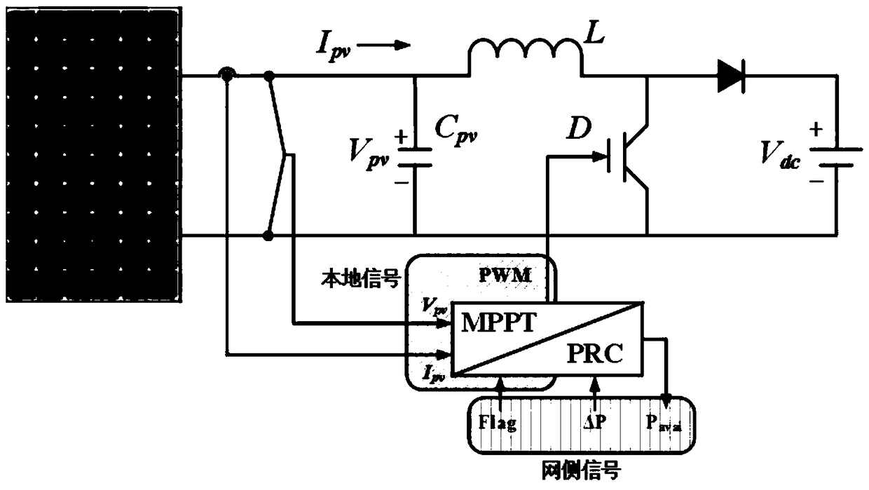
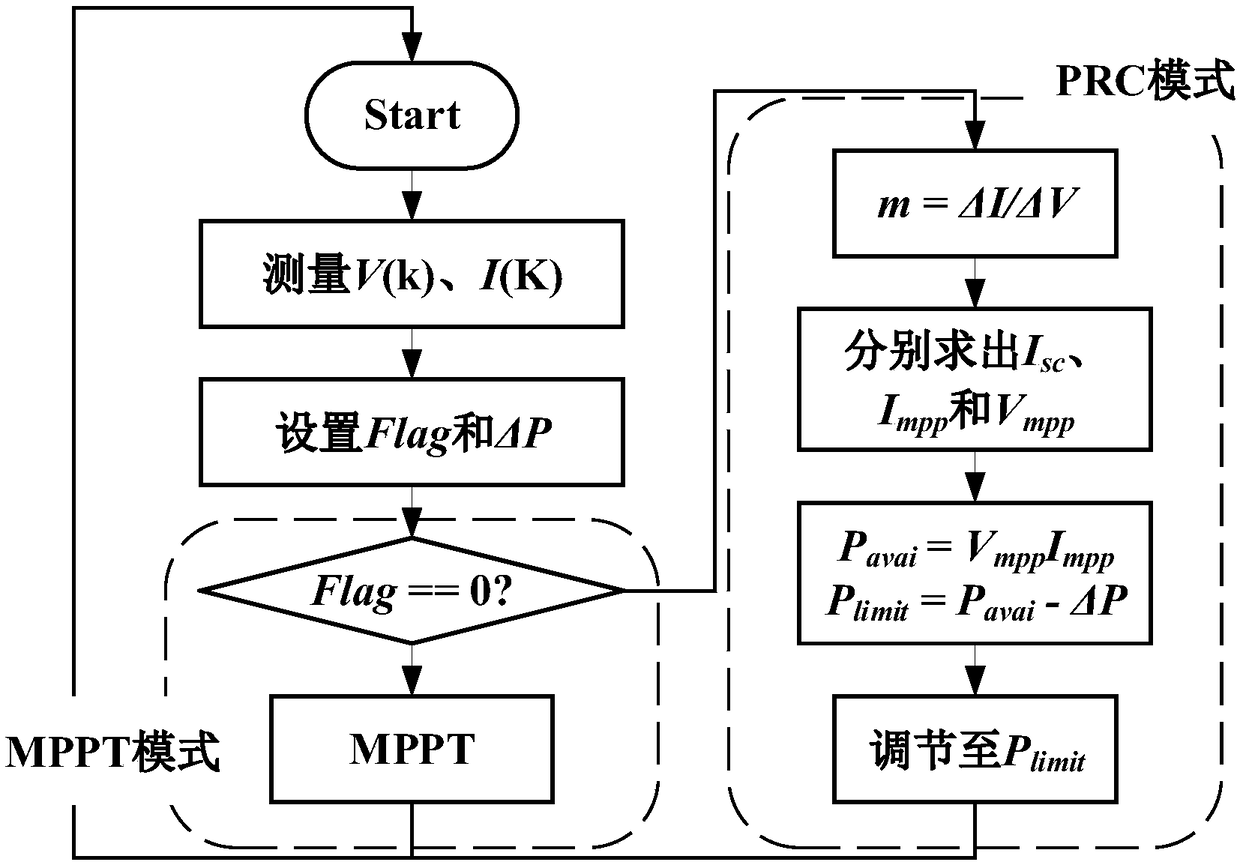
[0032] Such as figure 2 , 3 As shown, the algorithm proposed by the present invention mainly includes two working modes, that is, MPPT mode and PRC mode; algorithm signals can also be divided into local signals and network measurement signals. The local signal samples the voltage and current of the photovoltaic (V pv , I pv ), and then generate a PWM signal to control the photovoltaic system according to the algorithm. The network test signal is based on the operation status of the power grid, and the two working modes are switched by adjusting the signal Flag, and then the P avai Prediction is made and finally ΔP is adjusted in response to grid frequency changes.

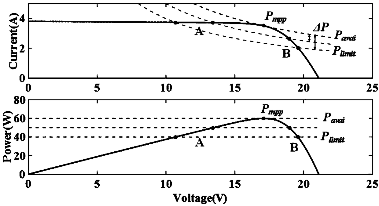
[0033] Figure 4 for P avai Forecast schematic. from Figure 4 It can be seen that when the system works in the case of A, the operating point is actually located on the left side of the photovoltaic I-V curve, that is, the constant current region. The value of m can be obtained by perturbing around A, na...


PUM


Abstract

The invention discloses a novel photovoltaic reserve power control method. The method comprises the steps that the voltage and current of a photovoltaic system are sampled, and a voltage value V(k) and a current value I(k) are obtained; an adjusting signal is sent according to the running state of a power grid to control work modes of the photovoltaic system, wherein the work modes include a maximum power point tracking mode and a reserve power control mode; in the reserve power control mode, the current photovoltaic output power P<pv> is adjusted to be P<limit> below MPP, and the value of theshort-circuit current I<sc> is calculated; the value of the maximum power point current I<mpp> is obtained; according to photovoltaic output characteristics, the maximum power point voltage V<mpp> isobtained; P<avai> is obtained, and a work point is adjusted according to the photovoltaic reserve power deltaP. By means of the method, the photovoltaic maximum output power can be predicted accurately in real time, and the change of the photovoltaic reserve power can be quickly adjusted.

Description

technical field [0001] The invention relates to a method for controlling photovoltaic reserve power, in particular to a novel method for controlling photovoltaic reserve power, which can accurately predict the maximum output power of photovoltaics in real time and quickly adjust changes in photovoltaic reserve power. Background technique [0002] As the penetration rate of new energy power generation continues to increase, it has also caused many adverse effects on the power grid. These impacts seriously restrict the large-scale development of the new energy industry, and even lead to the repeated power cuts of the large-scale wind farms and photovoltaic power stations that have been built, resulting in a huge waste of resources. [0003] In order to overcome these adverse effects, the current main idea is to use a hybrid system of new energy and energy storage to participate in frequency modulation and achieve smooth power output. However, due to the high cost and short li...

Claims


Application Information

Patent Timeline
Patent Type & Authority Applications(China)
IPC IPC(8): G05F1/67
CPCG05F1/67Y02E10/56
Inventor 李星硕文辉清
Owner XIAN JIAOTONG LIVERPOOL UNIV
Why Eureka
Try Eureka