Cable connecting terminal and cable

A terminal and cable technology, which is applied to the end parts of multi-core cables, conductive connections, circuits, etc., can solve problems such as failures and accidents, increase in temperature rise, and increase in contact resistance between cables and terminals. The effect of good connection performance, high strength and good quality

Pending Publication Date: 2019-03-19
HUNAN XIANGNENG ELECTRIC WORKS
View PDF6 Cites 3 Cited by
  • Summary
  • Abstract
  • Description
  • Claims
  • Application Information

AI Technical Summary

Problems solved by technology

In turn, the contact resistance of the connection between the cable and the terminal increases, and the temperature rise increases during long-term...

Method used


Image

  • Cable connecting terminal and cable
  • Cable connecting terminal and cable
  • Cable connecting terminal and cable

Examples


Embodiment 1

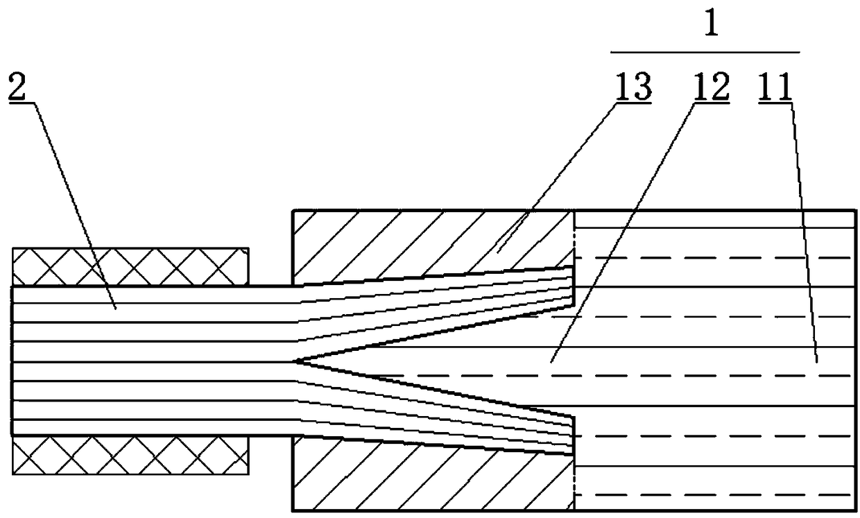
[0037] Such as figure 1 As shown, the cable terminal 1 includes a fixedly connected working end 11 and a clamping section. The mandrel 12 of the clamping section is integrally formed with the working end 11 and is made of red copper. The working end 11 can be an in-line terminal, a pin type, a nose type or a right-angle type, etc.

[0038] The sleeve 13 is made of aluminum alloy, coaxially arranged with the mandrel 12, and fixedly connected with the working end 11 by means of friction welding. Other welding methods can also be used, or the inner diameter of the sleeve 13 is matched with the outer diameter of the working end 11, and then crimped or welded by electromagnetic pulse.

[0039] Take the working end 11 as the root of the mandrel 12 and the sleeve 13, and the other end as the head.

[0040] The outer peripheral surface of the mandrel 12 is conical, and the inner peripheral surface of the sleeve 13 is conical, forming a cylindrical accommodating space between them. ...

Embodiment 2

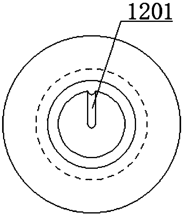
[0043] Based on Example 1, such as image 3 As shown, the outer periphery of the mandrel 12 includes a longitudinal escape groove. In this way, the front end of the mandrel 12 is in the shape of a circular arc. When the conductive wire bundle extends into the accommodation space, the conductive wire at the central axis is embedded in the avoidance groove, and the whole conductive wire bundle is stretched by the mandrel 12 and evenly scattered into the accommodation space. space.

Embodiment 3

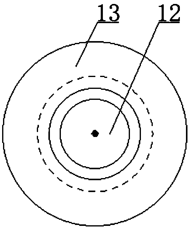
[0045] Such as Figure 4 As shown, the wall thickness of the sleeve 13 is uniform, so that the sleeve 13 can be formed by stamping and forging a straight cylinder, which is convenient to manufacture. Friction welding with the working end 11.


PUM


Abstract

The invention relates to a cable connecting terminal comprising a working end and a clamping end that are fixedly connected. The clamping end includes a mandrel and a sleeve that are arranged coaxially; the head of the clamping end points to the root direction; and the outer diameter of the mandrel is gradually increased and the inner diameter of the sleeve is gradually increased. Accommodation space is formed between the mandrel and the sleeve; and the random radial cross-sectional area of the accommodation space is not less than the cross-sectional area of a conductive wire bundle. Accordingto the cable connecting terminal, the contact area with the conductive wire bundle of the cable is increased and the resistance is low; and compared with the existing cable terminal, the provided cable connecting terminal is shorter. The connection is done closely and the connection strength is enhanced.

Description

technical field [0001] The invention relates to the field of cables, in particular to a cable terminal. The invention also relates to a cable. Background technique [0002] The conductive cables of cables above 4 levels use multi-strand wires to integrate wiring harnesses, and when the cable ends need to be wired, terminal blocks should be used. If the existing connecting terminal is improperly operated during the crimping process, the contact area between the connecting terminal and the wire harness may be insufficient and the resistance may be too large. [0003] In order to meet the lightweight and low-cost requirements of high-voltage wire harnesses for new energy vehicles, traditional copper wire harnesses will gradually be replaced by aluminum alloy wire harnesses that are lighter in weight and lower in cost. However, after the aluminum alloy material is exposed to the air, a dense oxide film will quickly form on its surface. In turn, the contact resistance of the c...

Claims


Application Information

Patent Timeline
IPC IPC(8): H01R11/11H01R4/50H01R4/62
CPCH01R4/5016H01R4/625H01R11/11H01R2201/26
Inventor 陈善求杨志强阳文锋
Owner HUNAN XIANGNENG ELECTRIC WORKS
Why Eureka
Try Eureka