Supercharge Your Innovation With Domain-Expert AI Agents!

Rotary pressure reaction furnace

A pressure reaction, rotary technology, applied in the field of pressure vessel equipment, can solve the problems of inability to meet high pressure environment, no explosion-proof measures, no clear reactor pressure, etc., and achieve the effect of shortening manual operation time, shortening production cycle and simple structure

Inactive Publication Date: 2019-03-22
WUHAN UNIV OF SCI & TECH
View PDF7 Cites 1 Cited by
  • Summary
  • Abstract
  • Description
  • Claims
  • Application Information

AI Technical Summary

Problems solved by technology

This rotary kiln type reactor can be used for continuous production, and the inside of the kiln is slightly positive pressure, which can realize automatic loading and unloading. The disadvantage is that the rotary dryer operates under slight positive pressure or does not bear pressure
The disadvantage is that the reformer is a carbonization furnace for biomass materials, and the temperature is generally about 800°C. Other reactions above this temperature range cannot be carried out in this furnace, and the operation process of the reformer cannot meet the high pressure environment, so its There are no relevant explosion-proof measures
However, the pyrolysis reactor does not specify whether the reactor can withstand a certain pressure, and there are no relevant explosion-proof measures. In addition, when feeding and discharging the device, the furnace body needs to be rotated to an angle of about 35° to 60° to enter and discharge the material.

Method used


Image

  • Rotary pressure reaction furnace
  • Rotary pressure reaction furnace

Examples


Embodiment 1

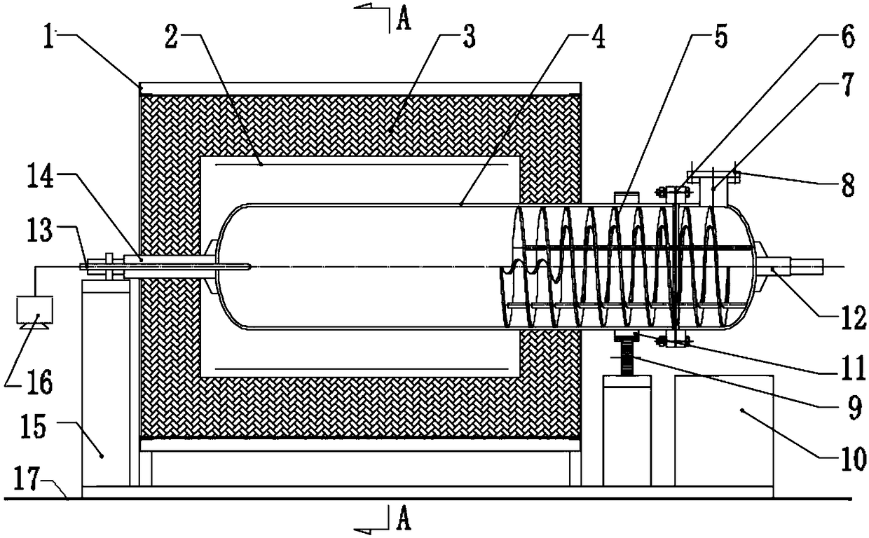
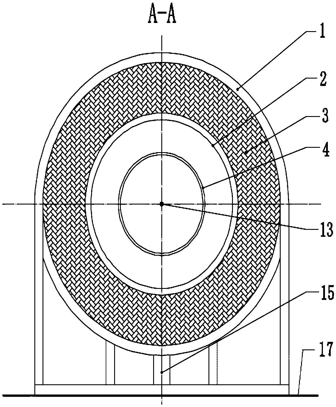
[0024] Embodiment 1: the present invention provides a kind of rotary pressure reaction furnace, its structure is as figure 1 , figure 2 As shown in the figure, it can be seen that the rotary pressure reaction furnace includes at least a heating furnace and a reactor 4. The heating furnace is fixed on the foundation 17 through a furnace steel structure 1. The furnace steel structure of the heating furnace is cylindrical, round A furnace body refractory material layer 3 is built inside the cylinder, and the heating device 2 is installed on the axial inner wall of the furnace body refractory material layer, so that the annular heat source of the heating device surrounds the reactor; Device 5, maintenance flange 6, material inlet and outlet 7, explosion-proof device 8, transmission device 9, transmission rack 11, gas inlet and extraction device 12, detection device 13 and control system 16, and a hopper 10 is also provided.

[0025] The reactor 4 is a long cylinder with both end...


PUM


Abstract

The invention relates to a rotary pressure reaction furnace. The rotary pressure reaction furnace comprises a heating furnace and a reactor, wherein the furnace body steel structure of the heating furnace is cylindrical; a cylinder is internally provided with a furnace body refractory material layer and a heating device; the reactor is a long cylinder of which two ends are sealed, the reactor is coincided with two axial lines of the heating furnace, one section of the reactor is arranged in the heating furnace and is used as a material reaction zone, the other section is arranged outside the heating furnace, and the reactor is provided with an overhauling flange, a material feeding and discharging opening, an explosion-proof device and a gas introducing and drawing device from left to right; a transmission gear rack is welded at the outer side of the reactor, a transmission device is connected with the reactor through the transmission gear rack, the transmission gear rack is driven torotate through the transmission device, the reactor and a material feeding and discharging spiral conveyor therein can rotate along with the transmission gear rack, and a motor in the transmission device controls the reactor to rotate forwardly and reversely; a discharging funnel is arranged under the reactor. The rotary pressure reaction furnace disclosed by the invention is simple in structure,has the functions of rotationally and uniformly mixing materials, preventing explosion and automatically feeding and discharging the materials, reaction of powdery materials can be safe and reliable,and the production requirements of various powdery materials under high temperature and high pressure can be met.

Description

technical field [0001] The invention relates to a pressure vessel equipment with rotating function, in particular to a rotary pressure reaction furnace. Background technique [0002] In the field of powder material reaction, in order to mix the reactants evenly, a rotary reactor is often used. The common one is the rotary kiln type reaction furnace, which has a certain installation inclination angle, and the kiln is equipped with a lifting plate. For example, Chinese patent application number: 2014106757833, the disclosed powder coating rotary dryer, when working, the kiln body rotates, and the material rolls up and down under the action of the lifting plate in the kiln to achieve a good mixing effect; in addition, the material is in the kiln. Under the action of the inclination angle of the kiln body, it rolls and spirals forward from the material inlet to the material outlet and discharges out of the kiln body. This rotary kiln type reaction furnace can be used for conti...

Claims


Application Information

Patent Timeline
IPC IPC(8): B01J19/28B01J4/00B01J3/04
CPCB01J3/04B01J4/001B01J19/28
Inventor 潘妮高标付继江戴方钦
Owner WUHAN UNIV OF SCI & TECH
Features
  • R&D
  • Intellectual Property
  • Life Sciences
  • Materials
  • Tech Scout
  • Unparalleled Data Quality
  • Higher Quality Content
  • 60% Fewer Hallucinations
Learn More