Transportation equipment convenient for transferring silicon cutting slag

A transportation equipment, silicon cutting technology, applied in solid separation, sieve, grid, etc., can solve the problem that the hopper cannot classify and transport silicon materials and silicon slag of different sizes, and cannot screen and screen silicon materials and silicon slag, Recycle silicon material and silicon slag to achieve the effect of improving service life, reducing wear and protecting the surface

Inactive Publication Date: 2019-03-22
新疆泰宇达环保科技有限公司
View PDF6 Cites 4 Cited by
  • Summary
  • Abstract
  • Description
  • Claims
  • Application Information

AI Technical Summary

Problems solved by technology

[0005] The purpose of the present invention is to provide a transportation device that facilitates the transfer of silicon cutting slag, so as to solve the problem that traditional hoppers cannot classify and transport silicon materials and silicon slag of different sizes, and that silicon materials and silicon slag cannot be further screened during transportation. To maximize the screening and recovery of silicon materials and silicon slag

Method used


Image

  • Transportation equipment convenient for transferring silicon cutting slag
  • Transportation equipment convenient for transferring silicon cutting slag

Examples


Embodiment 1

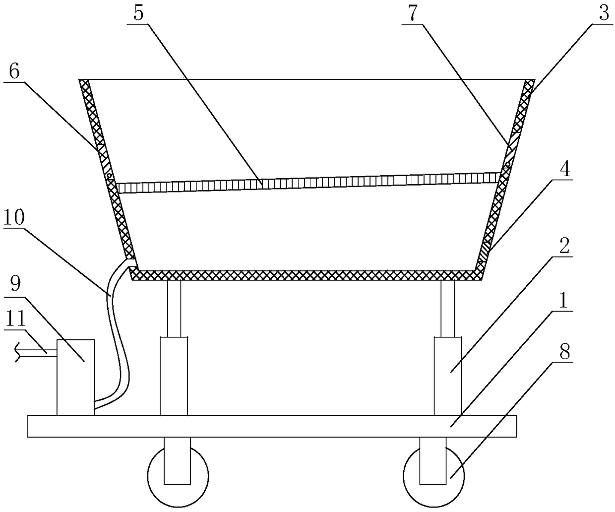
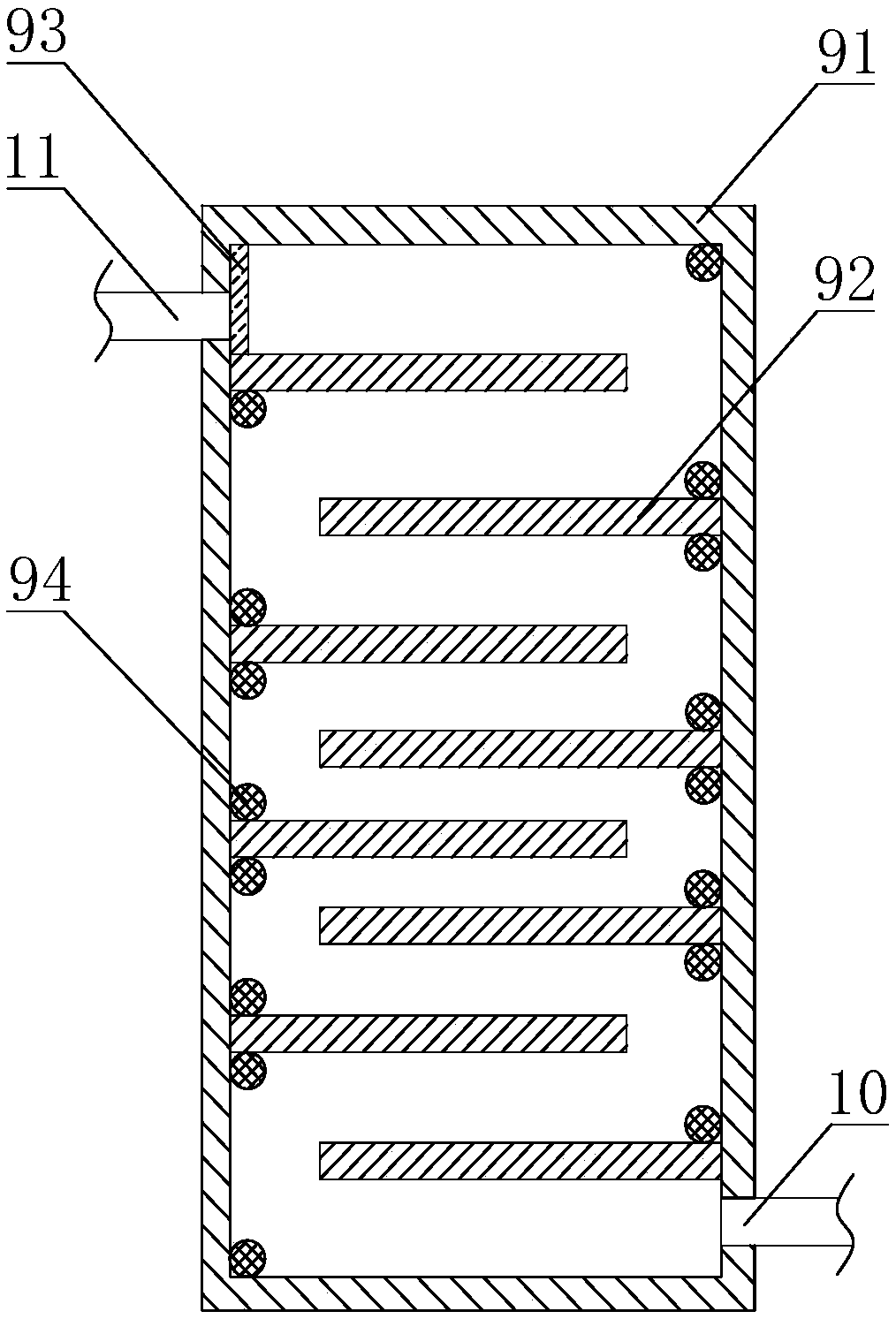
[0039] Such as figure 1 and figure 2 The transportation equipment shown is convenient for the transfer of silicon cutting slag, including a base 1, the bottom of the base 1 is provided with a universal wheel 8, the base 1 is provided with a hydraulic cylinder 2, and the top end of the piston rod of the hydraulic cylinder 2 is fixedly connected There is a sieve hopper 3, the sieve plate 5 is arranged in the sieve hopper 3, the wall surface of the sieve hopper 3 is provided with a feed port and a discharge port located above the sieve plate 5, and a feed plate 7 is arranged in the feed port , a discharge plate 6 is arranged in the discharge opening, and a slag inlet and a slag discharge outlet located below the sieve plate 5 are also arranged on the wall surface of the sieve hopper 3, and a slag inlet plate 4 is arranged in the slag inlet, and the slag outlet passes The slag pipe 10 is connected with a filter box 9, the filter box 9 includes a housing 91, the casing 91 is prov...

Embodiment 2

[0043] Such as figure 1 As shown, on the basis of Embodiment 1, the feed plate 7 is hinged in the feed port, the discharge plate 6 is hinged in the discharge port, and the slag feed plate 4 is hinged in the slag feed port; the sieve plate 5 is close to One end of the feed plate 7 is higher than the end of the sieve plate 5 close to the discharge plate 6; the angle between the sieve plate 5 and the horizontal plane is 5-15°; the aperture of the sieve plate 5 is 1.2mm.

[0044] When loading, adjust the height of the sieve hopper 3 through the hydraulic cylinder 2, open the feed plate 7 to feed silicon material above the sieve plate 5, then adjust the height of the sieve hopper 3, open the slag feed plate 4 to feed silicon slag under the sieve plate 5 . After the feeding is completed, push the base 1 to move to move the silicon material and silicon slag to the designated place. During the moving process, part of the silicon slag breaks away from the silicon material during the s...


PUM


Abstract

The invention discloses transportation equipment convenient for transferring silicon cutting slag. The transportation equipment comprises a pedestal, a hydraulic cylinder and a sieving hopper, whereina sieving plate is arranged in the sieving hopper; a feed inlet and a feed outlet above the sieving plate are formed in the wall surface of the sieving hopper; a feeding plate is arranged in the feedinlet and a discharge plate is arranged in the feed outlet; a slag inlet and a slag outlet below the sieving plate are also formed in the wall surface of the sieving hopper; a slag inlet plate is arranged in the slag inlet and a filter tank is connected with the slag outlet through a slag inlet pipe; the filter tank comprises a shell, an exhaust tube above the slag inlet pipe is arranged on the shell, and a filter screen is arranged on the exhaust tube; a plurality of slag traps parallel to a horizontal plane are arranged in the shell from top to bottom; and a through hole is formed in each of the slag traps to communicate with the top of each of the slag traps and the bottom of each of the slag traps. According to the transportation equipment, silicon slags and silicon materials with different sizes can be classified and transported in batches, in addition, the silicon slags and the silicon materials can be further sieved in a transportation process, and the silicon slags detached from the silicon materials are fallen into a silicon slag placement cavity and are collected.

Description

technical field [0001] The invention relates to the field of silicon waste recycling, in particular to a transportation device for transferring silicon cutting slag. Background technique [0002] Polycrystalline silicon is made into a silicon wafer to be processed after ingot casting, ingot breaking, slicing and other procedures, and a small amount of boron and phosphorus are doped and diffused on the silicon wafer to form a P-N junction. Then use screen printing to print the finely prepared silver paste on the silicon wafer to make a grid line, and after sintering, make a back electrode at the same time, and coat a layer of anti-reflective coating on the surface with the grid line, and the battery sheet is This is done. [0003] During the cutting process of silicon wafers, more silicon slag will be produced, and recycling the silicon cutting slag can significantly reduce the production cost. Before the recovery process of silicon cutting slag, pretreatment processes such...

Claims


Application Information

Patent Timeline
IPC IPC(8): B07B1/28B07B1/42B07B1/46
CPCB07B1/005B07B1/28B07B1/42B07B1/46B07B1/4609
Inventor 周旭庹开正
Owner 新疆泰宇达环保科技有限公司
Why Eureka
Try Eureka