Method for reinforcing concrete floor by H-shaped steel

A technology of H-beam and concrete, applied in the direction of building maintenance, construction, building structure, etc., to achieve the effect of simple process, fast speed and improved safety

Inactive Publication Date: 2019-03-22
SHANDONG JIANZHU UNIV
View PDF5 Cites 2 Cited by
  • Summary
  • Abstract
  • Description
  • Claims
  • Application Information

AI Technical Summary

Problems solved by technology

However, in the existing method of adding H-shaped steel beams on the bottom of the floor, the floor and the H-shaped steel are not effectively connected to form a whole to bear the force

Method used


Image

  • Method for reinforcing concrete floor by H-shaped steel
  • Method for reinforcing concrete floor by H-shaped steel
  • Method for reinforcing concrete floor by H-shaped steel

Examples


Embodiment 1

[0065] Such as Figure 1-9 , Shown in 13, a kind of method that penetrates floor bolt fastening method and strengthens concrete floor, comprises the steps:

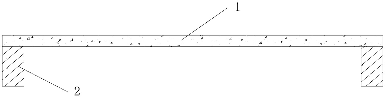
[0066] (1) vertically offer a hole 6 through the floor slab on the floor 1 according to the design position, and the aperture of the hole is 1mm larger than the diameter of the screw rod 13 passing through the hole;

[0067] (2) Install a 4mm thick steel backing plate 12 at the perforated position on the upper surface of the floor 1. The width and length of the steel backing plate 12 are the same as the upper flange 3 of the H-shaped steel beam to be fixed; the steel backing plate 12 needs to be drilled before installation , the hole matches the size and position of the hole on floor 1;

[0068] (3) Thread the screw rod 13 into the holes of the floor and the backing plate, and screw the nut 10 at the end where the screw rod 13 is located on the upper surface of the floor, so that the screw rod 13 is fixed in the holes of...

Embodiment 2

[0077] Such as Figure 1-9 , Shown in 13, a kind of method that penetrates floor bolt fastening method and strengthens concrete floor, comprises the steps:

[0078] (1) Vertically offer a hole 6 through the floor slab on the floor 1 according to the design position, and the aperture of the hole is 2mm larger than the diameter of the screw rod 13 passing through the hole;

[0079] (2) Install a 7mm thick steel backing plate 12 on the upper surface of the floor 1 where holes are drilled. The width and length of the steel backing plate 12 are the same as the upper flange 3 of the H-shaped steel beam to be fixed; the steel backing plate 12 needs to be drilled before installation , the hole matches the size and position of the hole on floor 1;

[0080] (3) Thread the screw rod 13 into the holes of the floor and the backing plate, and screw the nut 10 at the end where the screw rod 13 is located on the upper surface of the floor, so that the screw rod 13 is fixed in the holes of th...

Embodiment 3

[0089] Such as Figure 1-6 As shown in and 10-13, a method for reinforcing a concrete floor slab by bolting bolts at the bottom of the slab comprises the following steps:

[0090] 1) According to the design position, on the lower surface of the floor 1, set up the bolting hole 8 driven into the bottom of the board vertically upwards, and the hole depth of the bolting hole 8 driven into the bottom of the board is 75% of the thickness of the floor 1; and The hole diameter of the bolting hole 8 driven into the bottom of the plate is 2 mm larger than the diameter of the screw 13 passing through the hole; after cleaning the hole, pour structural glue into the hole;

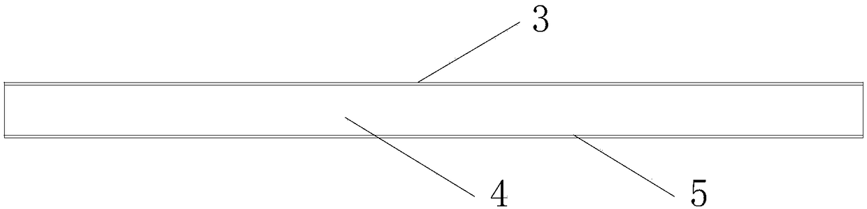
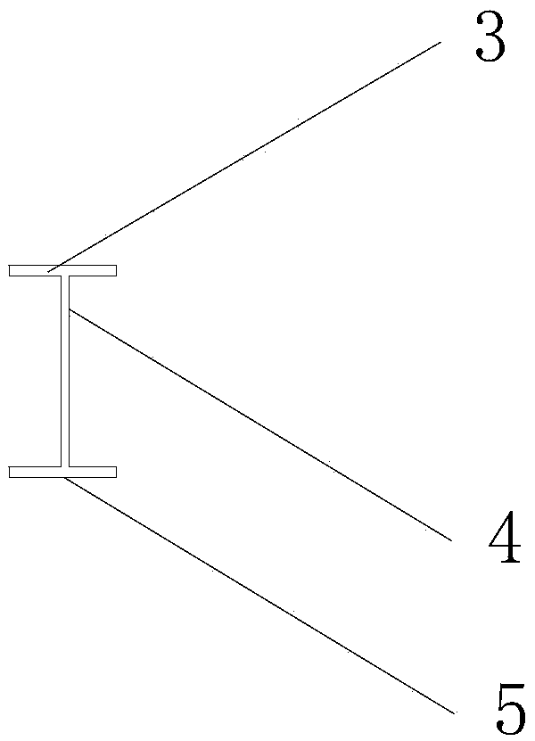
[0091] 2) implant one end of the screw rod 13 into the hole 6 punched through the floor in step 1), and the other end of the screw rod 13 is ready to install the H-shaped steel beam; the H-shaped steel beam is formed by the upper flange of the H-shaped steel beam 3. The web of the H-shaped steel beam 4 and the lower f...


PUM


Abstract

The invention relates to a method for reinforcing a concrete floor by H-shaped steel and belongs to the technical field of civil engineering. The method is a reinforcing method for improving the mechanical property of the floor by improving measures of connecting the floor and an H-shaped steel beam, and according to a bolt fixing method of connecting the floor and the H-shaped steel beam, the method is divided into a floor penetrating bolt fixing method and a plate bottom bolt fixing method. The H-shaped steel beam and the concrete floor are connected to be a whole through a bolt, common stress of the two can be ensured, the bearing capacity of the reinforced floor is obviously improved, and compared with a cast-in-place concrete beam construction method, the construction method is simplein process, fast in speed and more suitable for applications in reinforcement engineering.

Description

technical field [0001] The invention relates to the technical field of civil engineering, in particular to a method for reinforcing concrete floor slabs with H-shaped steel. Background technique [0002] With the development of social economy, people have higher and higher requirements for production and living space. Although rebuilding buildings can meet the large span and large space that people need for production and life, it will cause great waste. Therefore, the method of strengthening and transforming existing buildings is generally accepted. This method can solve the problem with less investment and shorter time. It is a common phenomenon to improve the use function of old buildings, but the biggest problem brought about by the function improvement is the change of floor load. If the floor load increases significantly, the bearing capacity and deformation requirements of the original floor slab design will not be satisfied. Therefore, it is necessary to carry out...

Claims


Application Information

Patent Timeline
Patent Type & Authority Applications(China)
IPC IPC(8): E04G23/02
CPCE04G23/0237
Inventor 赵考重王莉李安起闫凯
Owner SHANDONG JIANZHU UNIV
Why Eureka
Try Eureka