Eureka AIR delivers breakthrough ideas for toughest innovation challenges, trusted by R&D personnel around the world.

Method for determining ultrasonic-acoustic emission detection defect depth of composite material

A composite material and defect depth technology, which is applied in the direction of using sound wave/ultrasonic wave/infrasonic wave to analyze solids, analyze materials, and use sound wave/ultrasonic wave/infrasonic wave to analyze materials, etc. It can solve the requirements and limitations that are difficult to meet the requirements and limitations of accurate depth determination of defects Ultrasonic-acoustic emission method detection application, difficulty in determining the depth of detected defects, etc., to achieve good application applicability of engineering detection, conducive to popularization and application, and easy to operate and master

Active Publication Date: 2019-03-22
AVIC COMPOSITES
View PDF8 Cites 6 Cited by
  • Summary
  • Abstract
  • Description
  • Claims
  • Application Information

AI Technical Summary

Problems solved by technology

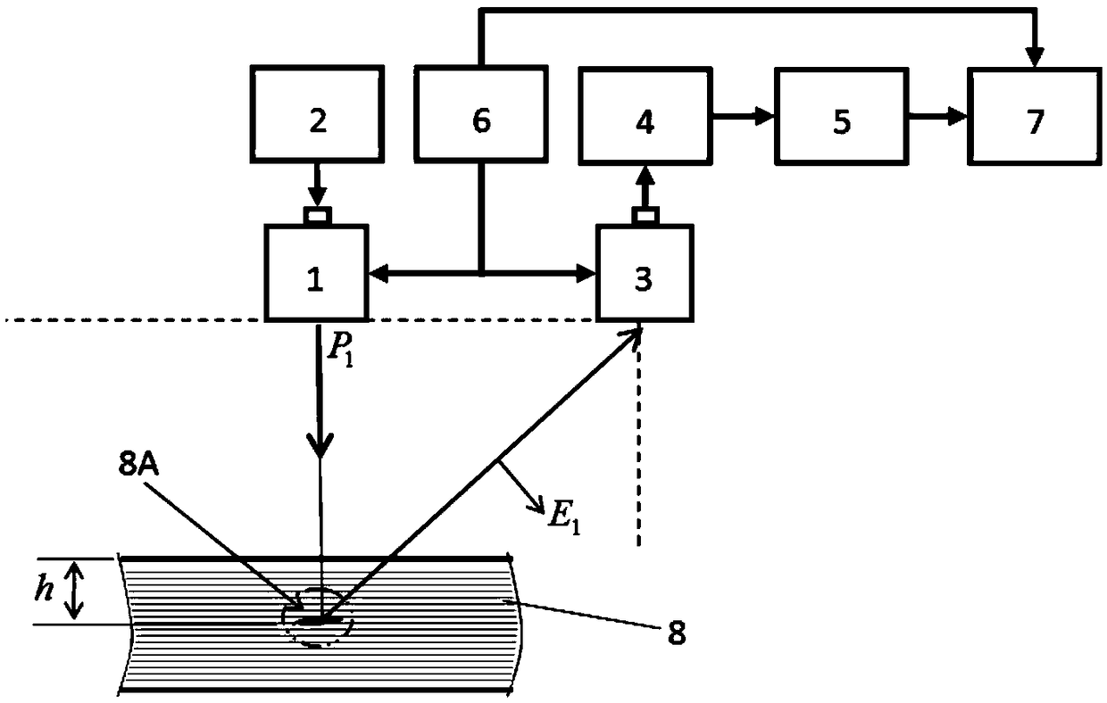
[0003] The obvious shortcoming of the current ultrasonic-acoustic emission detection method is that the horizontal distance from the detected defect to the receiving transducer can be roughly determined by using the transducer to receive the acoustic emission signal from the defect, but it is difficult to determine the depth of the detected defect. Moreover, due to the poor time-domain pulse characteristics and resolution of the traditional ultrasonic-acoustic emission detection signal, it is difficult to accurately determine the depth of the detected defect, let alone determine the detected defect, such as delamination defects, in the composite material structure. Therefore, it is difficult to meet the requirements for accurate depth determination of detected defects in the field of composite material detection, which limits the application of ultrasonic-acoustic emission method detection. However, the determination of the detected defect depth using the traditional ultrasonic thickness measurement principle requires Use a test block of known thickness to measure the sound velocity first, which is easy to introduce the deviation caused by the sound velocity measurement

Method used


Image

  • Method for determining ultrasonic-acoustic emission detection defect depth of composite material
  • Method for determining ultrasonic-acoustic emission detection defect depth of composite material
  • Method for determining ultrasonic-acoustic emission detection defect depth of composite material

Examples


preparation example Construction

[0050] 1) Preparation of thickness calibration test block

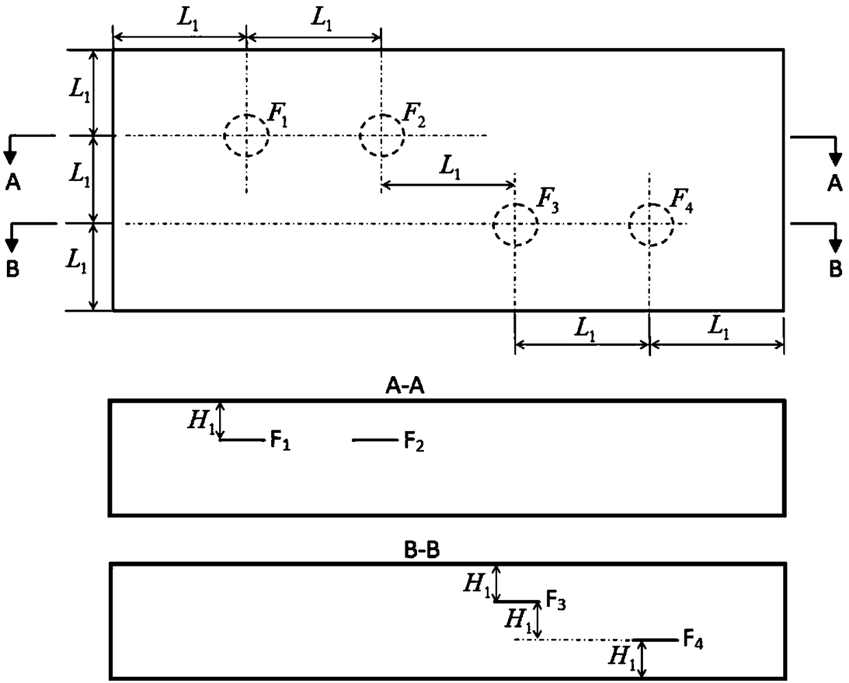
[0051] Using the composite material with the same molding process and material as the composite material to be tested, prepare a thickness calibration test block with a thickness of H. The thickness calibration test block is in the shape of a flat plate with equal thickness. There are 4 prefabricated pieces of the same size at different depths inside the thickness calibration test block. Defect F 1 , F 2 , F 3 , F 4 , its size is selected according to the detection requirements of the composite material structure 8 to be detected, and the defect F 1 , F 2 , F 3 , F 4 The center points of the thickness calibration test block are far away from each other in the plane direction L 1 , defect F 1 , F 2 , F 3 , F 4 The minimum distance between the center point of the thickness calibration test block and the edge near the edge of the thickness calibration test block is not less than L 1 , see figure 2 As shown,...

Embodiment

[0075]Using the method for determining the defect depth of ultrasonic-acoustic emission detection of composite materials in the present invention, select the high-resolution A-U ultrasonic-acoustic emission transducer produced by AVIC Composite Materials Co., Ltd., and use the MUT produced by AVIC Composite Materials Co., Ltd. -1. CUS-21J is used as an ultrasonic-acoustic emission detection instrument unit, and two kinds of thickness reference test blocks are prepared respectively with a carbon fiber composite material laminated structure, and the defect F 1 , F 2 , F 3 , F 4 Choose two different specifications of 3mm and 9mm in diameter respectively,

[0076] H=3mm, corresponding to 24 plies, the nominal thickness of a single ply is about 0.125mm, H 1 = 6 ply thicknesses,

[0077] H=20mm, the corresponding number of layers is 160, the nominal thickness of a single layer is about 0.125mm, H 1 = 40 ply thicknesses,

[0078] According to the defect detection method and ste...


PUM

PropertyMeasurementUnit
thicknessaaaaaaaaaa

Abstract

The invention belongs to a non-destructive testing technology, and relates to a method for determining ultrasonic-acoustic emission detection defect depth of a composite material in the fields of aviation, spaceflight, weapons, ships, metallurgy, steel, traffic, building and the like. The method comprises the following steps: firstly, preparing a thickness calibration test block; secondly, obtaining a thickness reference signal of the thickness calibration test block and checking the defect depth; finally, determining the detected defect depth. According to the method disclosed by the invention, by utilizing a time domain relation between n emission behavior of sound waves and defects in a detected material or the structure and adopting time-domain pulse characteristics of improved ultrasonic-acoustic emission signals, the ultrasonic-acoustic emission longitudinal resolution can be increased, and the defect depth can be more favorably and accurately detected; the method can be more easily realized, is very fast and easy to operate and master, and has better engineering detection and application practicability; the method is more beneficial for quality control of detection results,so that popularization and application of an ultrasonic-acoustic emission method can be more facilitated, and the ultrasonic-acoustic emission method can more favorably play a role in engineering.

Description

technical field [0001] The invention belongs to non-destructive testing technology, and relates to a method for determining the depth of defects detected by ultrasonic-acoustic emission of composite materials in the fields of aviation, aerospace, weapons, ships, metallurgy, steel, transportation, construction and the like. Background technique [0002] Because the ultrasonic-acoustic emission signal source comes from the inside of the detected part or structure, it is not sensitive to the orientation of defects and has stronger penetrating ability, so it is widely used in aerospace, weapons, electronics, ships, metallurgy, petrochemical oil, transportation, construction There are many unique applications in such fields, one of the important applications is the defect detection for composite materials and metal material structures. [0003] The obvious shortcoming of the current ultrasonic-acoustic emission detection method is that the horizontal distance from the detected de...

Claims


Application Information

Patent Timeline
Patent Type & Authority Applications(China)
IPC IPC(8): G01N29/07G01N29/30
CPCG01N29/07G01N29/30G01N2291/0231G01N2291/0289G01N2291/102
Inventor 刘松平刘菲菲傅天航李乐刚杨玉森李治应
Owner AVIC COMPOSITES
Why Eureka
Eureka Blog
Learn More