A method and system for calculating a ray trajectory point
A calculation method and track point technology, applied in the field of high-performance computing, can solve problems such as different calculations of calculation results, imprecise floating-point numbers, and inability to express accurately, so as to achieve the effects of improving accuracy, realizing tracking, and precise calculation
- Summary
- Abstract
- Description
- Claims
- Application Information
AI Technical Summary
Problems solved by technology
Method used
Image
Examples
Embodiment 1
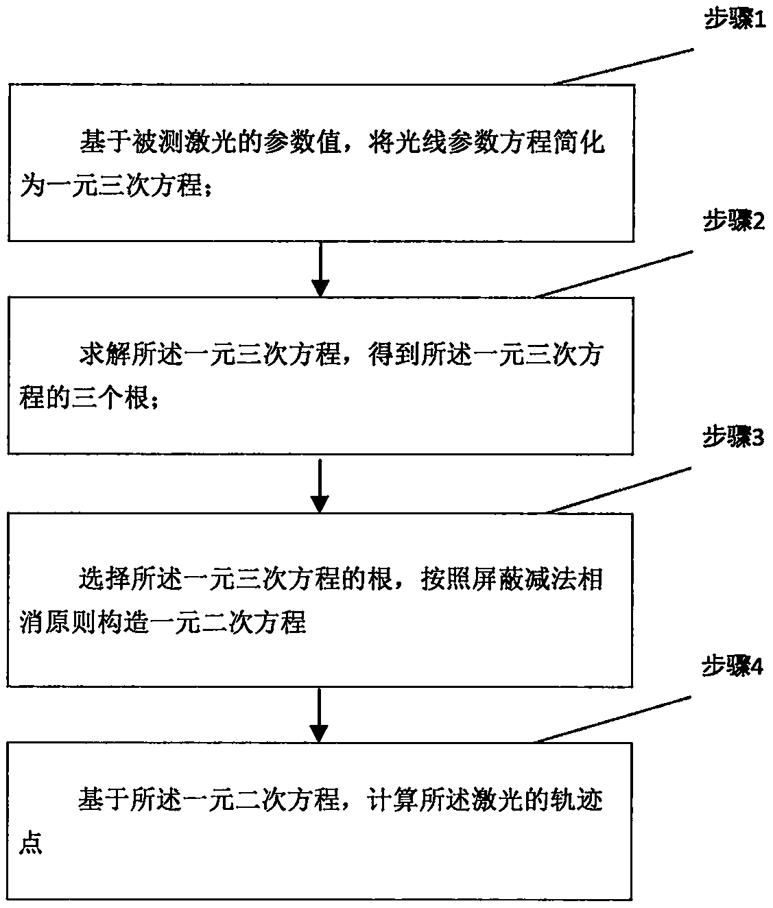
[0054] A light path tracing calculation method, such as figure 1 As shown, the method includes:
[0055] Step 1: Simplify the light parameter equation into a one-dimensional cubic equation based on the parameter value of the measured laser;
[0056] Step 2: solving the unary cubic equation to obtain three roots of the unary cubic equation;
[0057] Step 3: select the root of the unary cubic equation, and construct the unary quadratic equation according to the principle of shielding subtraction and cancellation;
[0058] Step 4: Calculate the trajectory point of the laser light based on the quadratic equation in one variable.
[0059] Specific steps are as follows:
[0060] Step 1: Based on the parameter value of the measured laser light, the light parameter equation is simplified into a unary cubic equation, and the light parameter equation includes a unary quartic equation;
[0061] Step 2: solving the unary cubic equation to obtain three roots of the unary cubic equation; ...
Embodiment 2
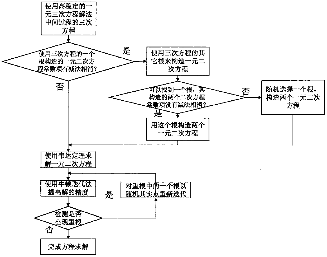
[0091] A method for calculating a ray trajectory point, comprising:
[0092] Step 1: Simplify the light parameter equation into a one-dimensional cubic equation based on the parameter value of the measured laser;
[0093] Step 2: solving the unary cubic equation to obtain three roots of the unary cubic equation;
[0094] Step 3: select the root of the unary cubic equation, and construct the unary quadratic equation according to the principle of shielding subtraction and cancellation;
[0095] Step 4: Calculate the trajectory point of the laser light based on the quadratic equation in one variable.
[0096] Such as figure 2 As shown, the specific steps are as follows:
[0097] Step 1: Based on the parameter values of the measured laser light, the light parameter equation is simplified into a unitary cubic equation, and the light line parameter equation includes a unitary quartic equation.
[0098] Under geometric optics approximation, the ray propagation equation can be ...
Embodiment 3
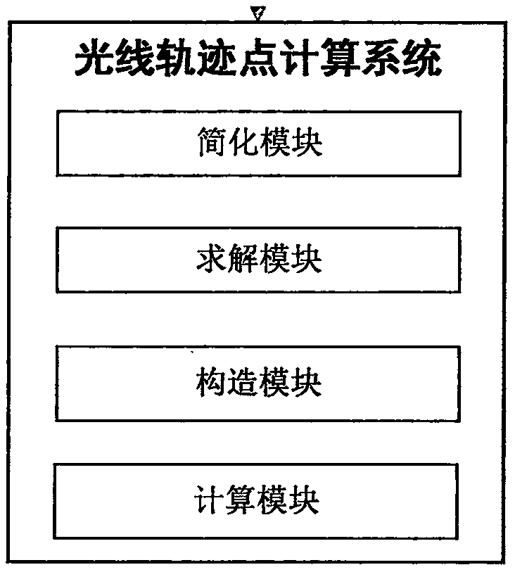
[0235] A ray trajectory point calculation system, such as image 3 As shown, the system includes a simplified module, a solution module, a construction module and a calculation module;
[0236] Simplification module: used to simplify the light parameter equation into a unary cubic equation based on the parameter value of the measured laser, and the light parameter equation includes a unary quartic equation;
[0237] Solving module: used to solve the unary cubic equation to obtain three roots of the unary cubic equation;
[0238] Construction module: for selecting the root of the unary cubic equation, and constructing the unary quadratic equation according to the principle of shielding subtraction and cancellation;
[0239] Calculation module: used to calculate the trajectory point of the laser light based on the quadratic equation in one variable.
[0240] Specifically, in the construction module, said selecting the root of said unary cubic equation, constructing a unary qua...
PUM
 Abstract
Description
Claims
Application Information
 - R&D
- Intellectual Property
- Life Sciences
- Materials
- Tech Scout
- Unparalleled Data Quality
- Higher Quality Content
- 60% Fewer Hallucinations
Browse by: Latest US Patents, China's latest patents, Technical Efficacy Thesaurus, Application Domain, Technology Topic, Popular Technical Reports.
© 2025 PatSnap. All rights reserved.Legal|Privacy policy|Modern Slavery Act Transparency Statement|Sitemap|About US| Contact US: help@patsnap.com


