
Electric spark linear cutting machine

A technology of cutting machine tools and electric discharge wires, which is applied in the field of CNC machine tools, can solve problems such as difficult adjustments, and achieve the effect of convenient clamping and clamping

Pending Publication Date: 2019-03-26
宁波市江北数控设备厂
View PDF1 Cites 3 Cited by
  • Summary
  • Abstract
  • Description
  • Claims
  • Application Information

AI Technical Summary

Problems solved by technology

[0002] The basic working principle of wire cutting machine tool is to use continuously moving thin metal wire (electrode wire) as electrode. Under the action of pulse power supply, spark discharge is formed between the electrode wire and the workpiece to be processed. The surface of the workpiece to be processed is melted or even vaporized, and the workpiece to be processed is moved along a predetermined trajectory, so as to achieve the purpose of processing the workpiece to be processed. At present, the workpiece to be processed is generally clamped on the wire cutting machine tool by a clamp, and the existing clamp is fixed On the mounting frame of the wire cutting machine tool, since most of the fixtures and the workpiece are fixedly connected, and most of the fixtures are fixed and non-adjustable, if the installation position of the workpiece and the fixture deviates, it will be very difficult to adjust, so People have begun to study a fixture that can adjust the position of the workpiece. For example, the Chinese invention patent (authorized announcement number: CN105665852B) discloses a wire electric discharge machine tool, including a column, a lower wire rack, an upper wire rack, a lower front guide wheel, and a lower rear guide. Wheel, upper front guide wheel, upper rear guide wheel, water spray plate, horizontal upper front guide wheel, horizontal lower front guide wheel, horizontal upper rear guide wheel, horizontal lower rear guide wheel, lower wire guide wheel, transmission guide wheel, upper wire Guide wheel, bed, wire storage cylinder base, wire storage cylinder, middle support plate, upper support plate, electrode wire A, electrode wire B, electrode wire C, electrode wire D, fixture, conductive block, lower wire rack and upper wire rack Set on the column, it is characterized in that: the front end of the lower wire frame and the front end of the upper wire frame are respectively equipped with two guide wheels, the front cantilever of the upper wire frame is set on the upper wire frame, the lower front guide wheel and the lower rear guide wheel are set on the lower wire frame, the upper front guide The upper and rear guide wheels are set on the upper wire frame, the water spray plate is respectively set on the lower wire frame, upper The upper rear guide wheel and the horizontal lower rear guide wheel are set on the column, the lower wire guide wheel is set on the rear end of the lower wire frame, the transmission guide wheel is set on the lower wire frame, the upper wire guide wheel is set on the column, and the base of the wire storage tube is set On the bed, the wire storage cylinder is set on the base of the wire storage cylinder; the column is set on the bed, the conductive block is respectively set on the column, the lower wire rack, the upper wire rack, and the front cantilever of the upper wire rack, and the middle supporting plate is set on the bed. The supporting plate is set on the middle supporting plate, the fixture is set on the upper supporting plate, and the processed parts are placed in the fixture. The wire electric discharge machine tool has four electrode wires for simultaneous processing, while effectively ensuring the machining accuracy and greatly improving the processing efficiency. , has obvious advantages for processing parts with a certain length. Only one axial movement is required to shape the width and thickness of the part. However, the relative position of the fixture of the machine tool and the workpiece cannot be adjusted, so the workpiece is clamped After being placed on the fixture, it cannot be adjusted at will, which will greatly increase the difficulty of the clamping work, and the four electrode wires need to work on four different planes. The winding path is long and has multiple turns, which will greatly speed up the electrode wire. The wear speed of the workpiece will reduce the reliability of the machine tool processing, and the four electrode wires process the workpiece at the same time. If the clamping position of the workpiece deviates, it will cause the four processing surfaces of the workpiece to deviate at the same time, which will greatly reduce the workpiece machining accuracy, and the machine tool can only process four For workpieces with regular surfaces, if special-shaped structures need to be processed, the electrode wires on the machine tool will inevitably be idle, which will also cause other electrode wires to be idle, increasing the use cost of the machine tool

Method used


Image

  • Electric spark linear cutting machine
  • Electric spark linear cutting machine
  • Electric spark linear cutting machine

Examples


Embodiment Construction

[0021] The specific implementation manners of the present invention will be further described below in conjunction with the accompanying drawings, so as to make the technical solution of the present invention easier to understand and grasp.

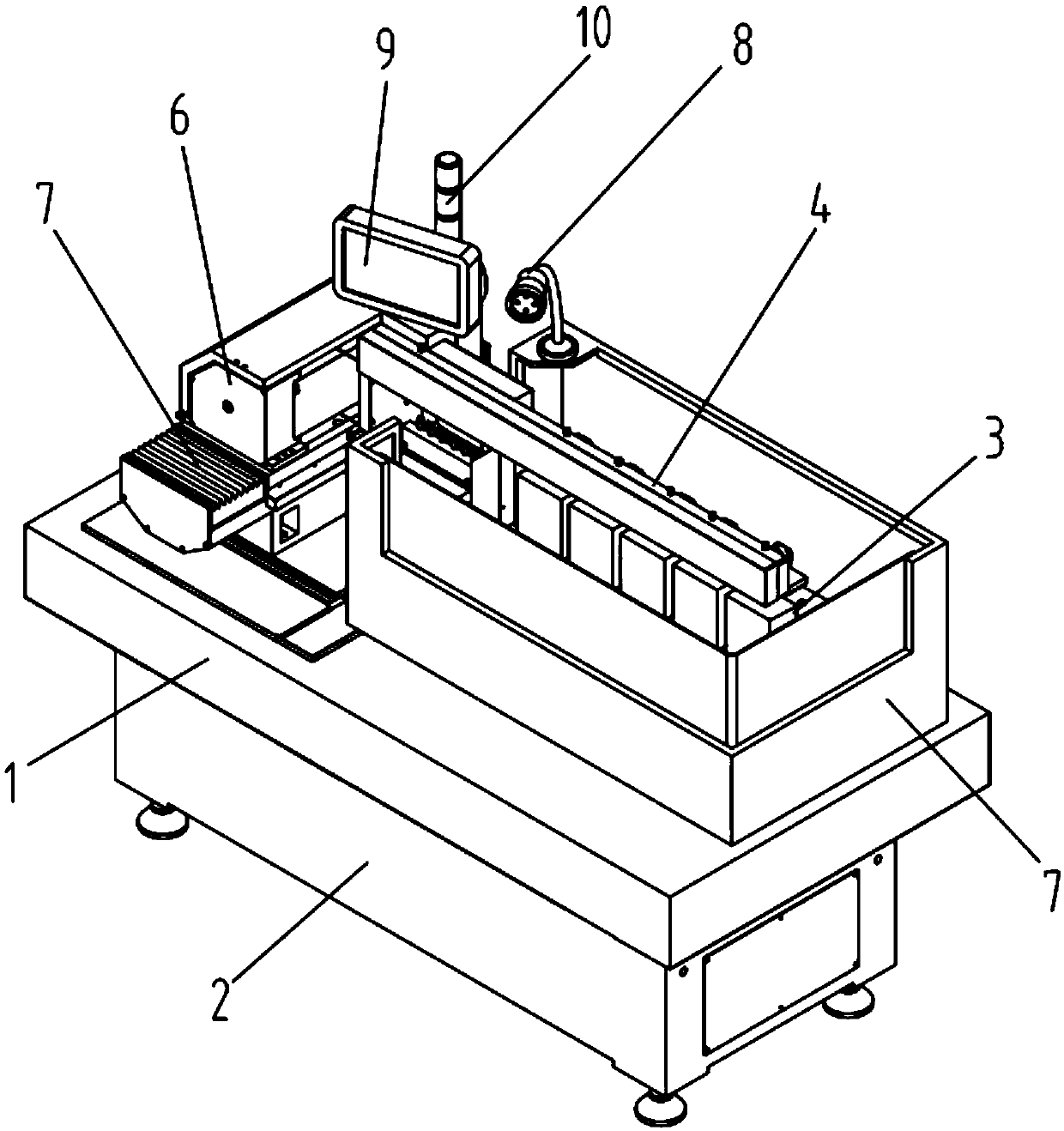
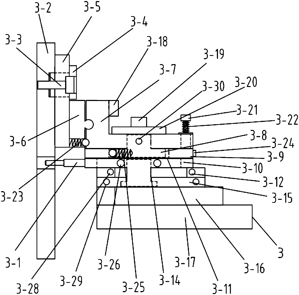
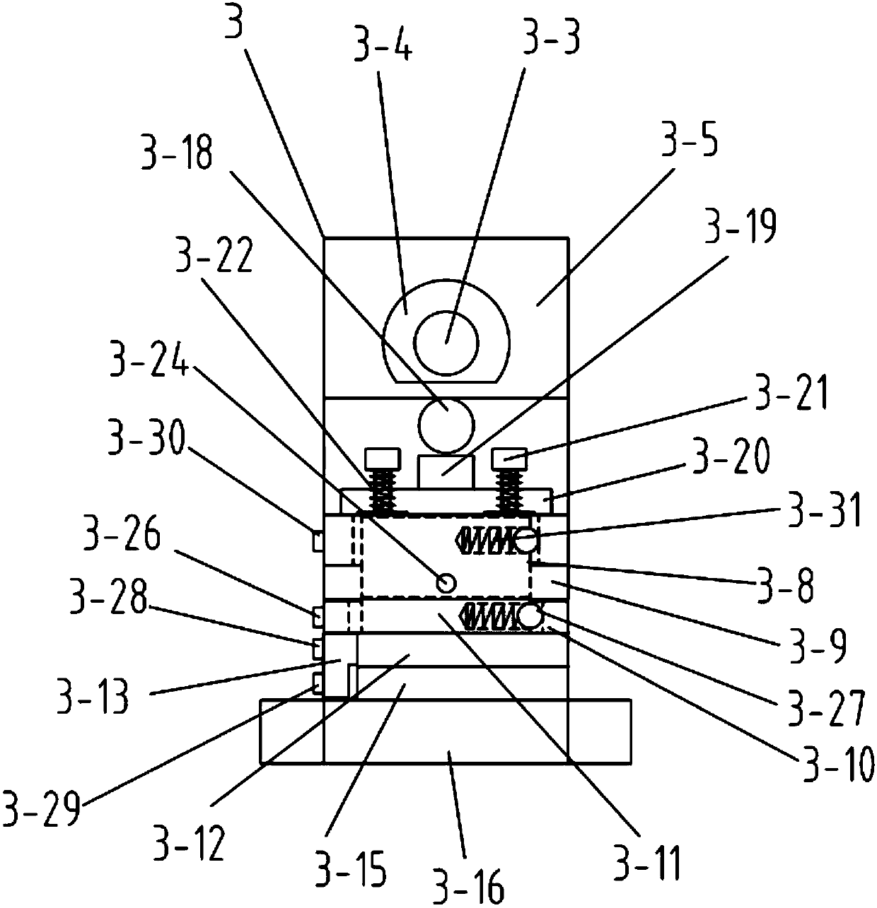
[0022] Such as Figure 1-5As shown, a wire electric discharge machine tool includes a bed 1 and a base 2, the base 2 is fixedly connected to the bed 1, and the bed 1 is provided with a universal fine-tuning mechanism 3 and a wire stand mechanism 4 , wire electrode 5, wire storage tube 6 and wire transport base 7, the wire transport base 7 is slidably connected with the wire storage tube 6, the wire storage tube 6 is connected with the wire stand mechanism 4 through the electrode wire 5, and the wire The frame mechanism 4 is located above the universal fine-tuning mechanism 3, and the universal fine-tuning mechanism 3 includes a connecting rod 3-1, an adhesive plate 3-2, a first bolt 3-3, a connecting column 3-4, and a first connecting pla...


PUM


Abstract

The invention relates to the field of numerical control machine tools, particularly to an electric spark linear cutting machine. The electric spark linear cutting machine comprises a machine body anda machine base, wherein a universal fine turning mechanism, a wire rack mechanism, a wire electrode, a wire storage barrel and a wire conveying base are arranged on the machine body; and the universalfine turning mechanism comprises a connecting rod, a pasting plate, a connecting pillar, a first connecting plate, a swinging plate, a first supporting plate, a first sliding block, a second supporting plate, a second sliding block, a supporting block, a rotating plate, a second connecting plate, a supporting shaft, a third supporting plate, a fourth supporting plate and a base. According to theelectric spark linear cutting machine, the supporting shaft is connected to the third supporting plate in a sleeving manner, the rotating plate and all structures on the rotating plate can rotate around the supporting shaft through the structure design, and a user conveniently adjusts the position of the pasting plate; and besides, the pasting plate is fixedly connected with an external to-be-processed workpiece, so that the processing position of the workpiece can be rotated to be slightly adjusted, and the user conveniently clamps the to-be-processed workpiece.

Description

technical field [0001] The invention relates to the field of numerical control machine tools, in particular to a wire electric discharge machine tool. Background technique [0002] The basic working principle of wire cutting machine tool is to use continuously moving thin metal wire (electrode wire) as electrode. Under the action of pulse power supply, spark discharge is formed between the electrode wire and the workpiece to be processed. The surface of the workpiece to be processed is melted or even vaporized, and the workpiece to be processed is moved along a predetermined trajectory, so as to achieve the purpose of processing the workpiece to be processed. At present, the workpiece to be processed is generally clamped on the wire cutting machine tool by a clamp, and the existing clamp is fixed On the mounting frame of the wire cutting machine tool, since most of the fixtures and the workpiece are fixedly connected, and most of the fixtures are fixed and non-adjustable, if...

Claims


Application Information

Patent Timeline
IPC IPC(8): B23H7/02B23H11/00
CPCB23H7/02B23H11/003
Inventor 徐建辉徐斌
Owner 宁波市江北数控设备厂
Learn More